Introduction
A comprehensive guide to bosch light relay wiring diagram instructions provides the technical foundation needed to install auxiliary lighting securely and efficiently in 12V and 24V DC automotive electrical systems. Auxiliary driving lights, high-output fog lamps, and heavy-duty work lights draw significant electrical current. Routing this high amperage directly through a dashboard switch causes thermal degradation, voltage drop, and switch failure. Implementing an electromechanical relay isolates the delicate cabin switch from heavy high-current loads, protecting the vehicle harness. Mechanics, technicians, and DIY enthusiasts rely on standardized terminal markings to configure these circuits correctly. Understanding these schematics improves troubleshooting accuracy, ensures reliable electrical connections, and prevents catastrophic failures like harness fires. Proper execution of relay wiring safeguards sensitive electronic modules while delivering maximum voltage directly to high-intensity lamps.
💡 Technical Key Takeaways:
- Core Focus: Diagnostic schematic and terminal connection layout for Bosch Light Relay Wiring Diagram Instructions.
- Target Scope: Field technicians, automotive DIYers, and residential/commercial electricians.
- Safety Rule: Always disconnect the primary power source/battery terminal and verify zero voltage with a multimeter before touching wires.
Core Concepts and Wiring Fundamentals
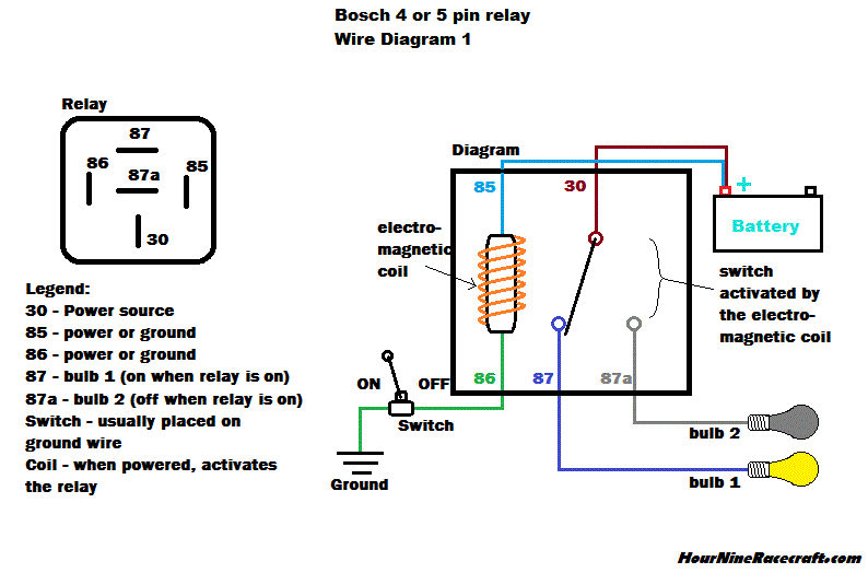
Automotive lighting circuits rely on two distinct electrical loops: a low-current control circuit and a high-current load circuit. The control circuit utilizes thin-gauge wire, a dashboard switch, and a fused ignition source to energize the relay coil. The load circuit utilizes heavy-gauge wire, an inline fuse connected directly to the battery positive terminal, and the high-wattage lighting load. An electromechanical relay operates via a copper wire coil wrapped around an iron core. When low-current power flows through the coil, a magnetic field pulls a spring-loaded armature downward. This physical movement closes internal contacts, completing the heavy-duty circuit that delivers power from the battery to the lamps. Fuses must be installed within inches of the power source on both circuits to protect against short circuits. Regional automotive standards, such as those governed by the Society of Automotive Engineers (SAE) in North America or equivalent international bodies, establish strict guidelines for wire gauge sizing and ampacity limits relative to circuit loads. Voltage drop across long wire runs must be minimized by selecting appropriate copper cross-sectional areas, especially when supplying high-amperage LED or halogen off-road light bars.
Electrical safety foundations emphasize that overloading undersized conductors with high-amperage loads is a primary cause of thermal events in mobile DC electrical architecture. — ESFI
Diagram Explanation and Key Components
Standard automotive relay schematics rely on universally recognized DIN terminal numbers stamped directly onto the housing of the component. Terminal 30 represents the unswitched power feed coming directly from the battery positive terminal through a dedicated fuse. Terminal 87 serves as the switched power output leading directly to the positive wire of the auxiliary light fixtures. Terminal 85 connects to the low-current control switch or ground trigger from the vehicle’s high-beam circuit. Terminal 86 completes the relay coil circuit by running to a clean, bare-metal chassis ground point. Some specialized relays include a Terminal 87a, which provides a normally closed contact output for alternating circuit applications, though standard single-pole single-throw auxiliary light setups leave this pin vacant. Reading these diagrams requires tracing the flow from the power source through the designated terminal numbers, referencing resources found in Relay and Component Wiring Diagrams for deeper structural insight. Color codes vary by region and aftermarket manufacturer; North American aftermarket kits frequently utilize yellow or red for battery feeds, black for grounds, and blue or green for switch triggers, whereas European harnesses may follow different standardized color conventions. Interpreting schematic lines, switch symbols, and fuse box icons accurately is fundamental to avoiding cross-connections and blown fuses during installation.
Common Problems and Troubleshooting Methods
Systematic diagnostic procedures for auxiliary lighting failures begin with verifying battery voltage at Terminal 30 using a digital multimeter. Common faults include blown fuses, oxidized chassis ground points, loose terminal crimps, and internal relay coil burnout. When lamps fail to illuminate upon activating the dashboard switch, the technician should first listen for an audible click emanating from the relay housing. A clicking sound indicates that the low-current control circuit (Terminals 85 and 86) is functioning correctly, pointing the diagnosis toward a fault in the high-current load circuit, such as a blown inline fuse at Terminal 30 or a severed wire leading to Terminal 87. The absence of a click points toward a control circuit failure, requiring voltage checks at the switch output and continuity tests across the coil pins. Technicians must always disconnect the vehicle battery before probing or repairing high-amperage supply lines to prevent accidental arcing. For broader context on reading schematic layouts and isolating wiring faults across diverse applications, reviewing materials within Wiring Diagram Basics and Wiring Troubleshooting helps build a structured methodology.
Practical Tips and Safety Considerations
High-current automotive electrical work demands rigorous adherence to safety protocols, including disconnecting the negative battery terminal before cutting, stripping, or terminating any power wire. Always mount the relay with the terminal prongs facing downward or sideways to prevent moisture, road salt, and debris from pooling inside the plastic connector housing. Utilize weather-pack sealed connectors and heat-shrink tubing with adhesive lining to protect crimped connections from galvanic corrosion in exposed under-hood environments. Wire gauge selection must match the total continuous current draw of the lighting array; utilizing conductors that are too thin will introduce excessive resistance, generating heat and reducing light output. Common mistakes include sharing an existing factory accessory ground with high-output auxiliary lights, which frequently overloads the factory wiring trace and causes intermittent flickering. Before finalizing any installation, double-check all connections against the intended schematic layout. For those expanding their technical knowledge into adjacent mobile systems, exploring Vehicle Wiring Diagrams offers valuable comparative references for complex multi-circuit harnesses.
Conclusion
Mastering bosch light relay wiring diagram instructions empowers technicians and DIY builders to design, install, and troubleshoot high-performance auxiliary lighting with absolute confidence. Separating the low-current dashboard control loop from the high-amperage lighting circuit prevents thermal overload, protects sensitive switches, and ensures maximum voltage delivery to the bulbs. Diligent adherence to standard terminal numbering, proper wire sizing, secure crimping practices, and robust weatherproofing guarantees long-term system reliability. Systematic diagnostic approaches prevent guesswork during fault isolation, saving time and preventing component damage. Maintaining strict safety precautions, including disconnecting power sources and verifying chassis grounds, remains essential for every automotive electrical project.
Quick Wiring Specifications & Terminal Guide
| Component / Circuit | Standard Wire Gauge | Recommended Protection |
|---|---|---|
| Control & Trigger Signals | 18 – 20 AWG | 5A – 7.5A Inline Fuse |
| Standard Auxiliary Load | 14 – 16 AWG | 15A – 20A Circuit Breaker |
| Main Power Feed / Supply | 10 – 12 AWG | 30A – 40A Heavy-Duty Relay |
Images References