Introduction
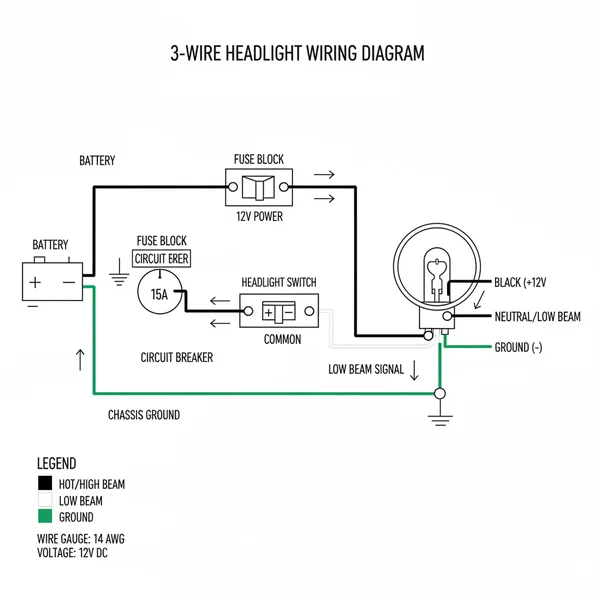
A 3 pin headlight plug diagram is a visual technical reference mapping the electrical pinout for standard three-terminal automotive headlamp connectors, most commonly associated with dual-filament bulbs like the H4 or 9003. This configuration handles low beam, high beam, and a shared circuit ground through a single molded plastic terminal housing. Understanding this layout matters because headlight circuits carry significant DC electrical current, often routed through dedicated relays and fuses to protect dashboard switches. Technicians and DIY enthusiasts rely on these schematics to diagnose lighting failures, perform headlight retrofits, or repair damaged wiring harnesses. Proper interpretation of these schematics ensures correct polarity, prevents premature bulb burnout, and maintains compliance with vehicle lighting standards governed by organizations like the Society of Automotive Engineers (SAE) or equivalent international bodies. Whether upgrading to modern optics or tracing an intermittent lighting fault, mastering this connection layout is essential for automotive electrical work.
💡 Technical Key Takeaways:
- Core Focus: Diagnostic schematic and terminal connection layout for 3 Pin Headlight Plug Diagram.
- Target Scope: Field technicians, automotive DIYers, and residential/commercial electricians.
- Safety Rule: Always disconnect the primary power source/battery terminal and verify zero voltage with a multimeter before touching wires.
Core Concepts and Wiring Fundamentals
Automotive lighting systems operate on 12V or 24V direct current (DC) power supplied from the vehicle battery and alternator circuit. The fundamental purpose of a 3 pin headlight plug is to distribute this electrical energy safely to dual-filament headlamp bulbs, which provide both low beam and high beam illumination from a single housing. Direct current flows from a power source through a fuse, passes through a control relay or multi-function dash switch, and terminates at the lamp connector.
Within the 3 pin terminal, current management requires distinct paths for each operational state. One terminal receives switched power for the low beam filament, a second terminal receives switched power for the high beam filament, and the third terminal serves as the common circuit ground returning current to the vehicle chassis. Understanding how these paths interact prevents cross-feeding voltage, which can inadvertently illuminate both filaments simultaneously and overheat the wiring harness.
Circuit protection is a critical element of vehicle lighting design. Automotive fuses isolate faults and prevent excessive current draw from melting insulation or damaging sensitive body control modules. When working with these circuits, technicians frequently consult Vehicle Wiring Diagrams to trace power distribution paths from the battery junction box all the way to the headlamp sockets.
[Finding] — According to the Society of Automotive Engineers (SAE), electrical connection resistance exceeding specified manufacturing tolerances in automotive lighting circuits is a primary contributor to voltage drop, resulting in reduced luminous output and premature thermal degradation of terminal housings.
Diagram Explanation and Key Components
Decoding a 3 pin headlight plug diagram requires recognizing standardized symbols, terminal designations, and wiring color codes. In a typical H4 or 9003 configuration, the triangular layout features three flat spade terminals arranged in a specific geometric pattern. The top terminal typically connects to the low beam power feed, the right terminal connects to the high beam power feed, and the left terminal acts as the dedicated system ground.
Standard schematics use specific line types and alphanumeric codes to identify each wire. Solid lines represent active power feeds, while dashed lines often indicate switched or auxiliary circuits. Color coding varies significantly between global regions and vehicle manufacturers. For example, North American vehicles often use specific factory color designations governed by manufacturer standards, whereas European and UK applications following BS standards may utilize distinct numbering or color schemes for lighting circuits.
Reading these technical drawings also involves understanding connector pin numbering. Manufacturers stamp small numeric identifiers—1, 2, and 3—onto the rear of the plastic plug housing near the wire entry points. Matching these physical numbers to the schematic ensures that power feeds do not get inverted with the ground wire, a mistake that can blow fuses or cause complex operational anomalies in switched-ground wiring systems common in certain imported vehicles.
Common Problems and Troubleshooting Methods
Headlight system diagnostics involve a systematic, step-by-step process to isolate open circuits, high-resistance connections, blown fuses, and compromised chassis grounds. One frequent failure point in high-current lighting connectors is thermal fatigue. Excessive electrical resistance at the spade terminals generates localized heat, melting the plastic housing and oxidising the metallic contacts. Technicians should always visually inspect the plug cavity for signs of discoloration or carbon buildup before testing electrical values.
Diagnostic procedures begin by disconnecting the 3 pin plug and utilizing a digital multimeter set to DC voltage. With the headlamp switch activated, the technician probes the low beam and high beam terminals against a known-good chassis ground to verify that system voltage is reaching the connector. If voltage is absent, the fault lies upstream in the fuse box, relay, or switch. If voltage is present but the bulb remains unlit, the technician measures continuity across the bulb filaments and checks the integrity of the ground wire returning to the frame.
Intermittent lighting issues often stem from loose terminal tension inside the molded plug housing. Over time, vibration causes the female spade receptacles to widen, creating a loose connection that arcs under heavy electrical load. When diagnosing complex electrical faults across multiple auxiliary systems, referencing Wiring Troubleshooting guides helps technicians streamline their diagnostic workflow and avoid unnecessary parts replacement.
Practical Tips and Safety Considerations
Working on automotive lighting circuits requires strict adherence to safe workshop practices, particularly regarding battery isolation and high-current electrical safety. Before servicing or repairing a headlight connector, always disconnect the negative battery terminal to prevent accidental short circuits, blown fuses, or personal injury from live electrical feeds. Additionally, never touch quartz-halogen bulb glass with bare fingers; oils from human skin create hot spots on the glass envelope during operation, causing premature bulb failure.
When repairing damaged wiring or replacing a melted 3 pin plug, technicians must select appropriate replacement wire gauge and high-temperature ceramic or OEM-grade nylon connector pigtails. Undersized wire cannot handle the continuous electrical load demanded by high-wattage headlamps, leading to voltage drop and potential fire hazards. Solder connections or approved crimp terminals equipped with waterproof heat-shrink tubing ensure long-term mechanical durability and environmental sealing against moisture intrusion.
Regional standards dictate specific installation parameters and beam alignment requirements for vehicle lighting modifications. Mechanics and builders must ensure that any aftermarket upgrades comply with local vehicle safety inspection codes, such as Department of Transportation (DOT) regulations in the US, Transport Canada guidelines, or equivalent statutory rules in the UK and Australia. For foundational knowledge on interpreting complex schematics across various electrical domains, reviewing Wiring Diagram Basics provides valuable context for reading technical drawings accurately.
Conclusion
Mastering the 3 pin headlight plug diagram bridges the gap between basic electrical theory and effective hands-on automotive repair. By understanding terminal pinouts, core power distribution concepts, and systematic diagnostic methodologies, technicians and DIY enthusiasts can resolve complex lighting failures safely and efficiently. Proper attention to wire sizing, terminal integrity, and regional safety standards ensures long-lasting repairs that maintain optimal vehicle visibility. Thorough preparation and methodical testing remain the foundational pillars of successful automotive electrical troubleshooting.
Quick Wiring Specifications & Terminal Guide
| Component / Circuit | Standard Wire Gauge | Recommended Protection |
|---|---|---|
| Control & Trigger Signals | 18 – 20 AWG | 5A – 7.5A Inline Fuse |
| Standard Auxiliary Load | 14 – 16 AWG | 15A – 20A Circuit Breaker |
| Main Power Feed / Supply | 10 – 12 AWG | 30A – 40A Heavy-Duty Relay |
Images References