Introduction
A 12v kids ride on car wiring diagram serves as the definitive roadmap for navigating the low-voltage direct current (DC) electrical circuits powering motorized toys. Battery-operated ride-on vehicles rely on closed-loop electrical systems to transfer energy from an onboard power source to electric drive motors, steering servos, and auxiliary accessories like headlights and sound modules. Mastering these schematics matters immensely for diagnosing intermittent failures, replacing worn-out switches, or upgrading stock components. Whether repairing a toy vehicle for household use or inspecting circuits within a commercial recreational setting, understanding these layouts improves diagnostic accuracy, prevents thermal overload, and ensures safe operation.
💡 Technical Key Takeaways:
- Core Focus: Diagnostic schematic and terminal connection layout for 12V Kids Ride On Car Wiring Diagram.
- Target Scope: Field technicians, automotive DIYers, and residential/commercial electricians.
- Safety Rule: Always disconnect the primary power source/battery terminal and verify zero voltage with a multimeter before touching wires.
Core Concepts and Wiring Fundamentals
Low-voltage ride-on toys operate primarily on 12-volt direct current, drawing power from a rechargeable sealed lead-acid or lithium-ion battery. This electrical ecosystem utilizes a simple circuit topology consisting of a power source, fuse protection, control switches, and DC electric motors. Unlike alternating current (AC) household circuits, DC systems require strict adherence to polarity, meaning positive and negative conductors must connect precisely to maintain correct motor rotation and prevent electronic module damage.
Fuses act as the primary line of defense against excessive current draw. When a drive wheel binds or a motor stalls, current surges through the wiring harness, generating heat. A properly rated thermal fuse or blade fuse interrupts the circuit by melting its internal link, halting the flow of electricity before wires melt or battery cells rupture. Regional standards governed by bodies such as the Society of Automotive Engineers (SAE) in North America outline strict parameters for low-voltage automotive harness design, wire gauge selection, and terminal crimping integrity to mitigate fire risks.
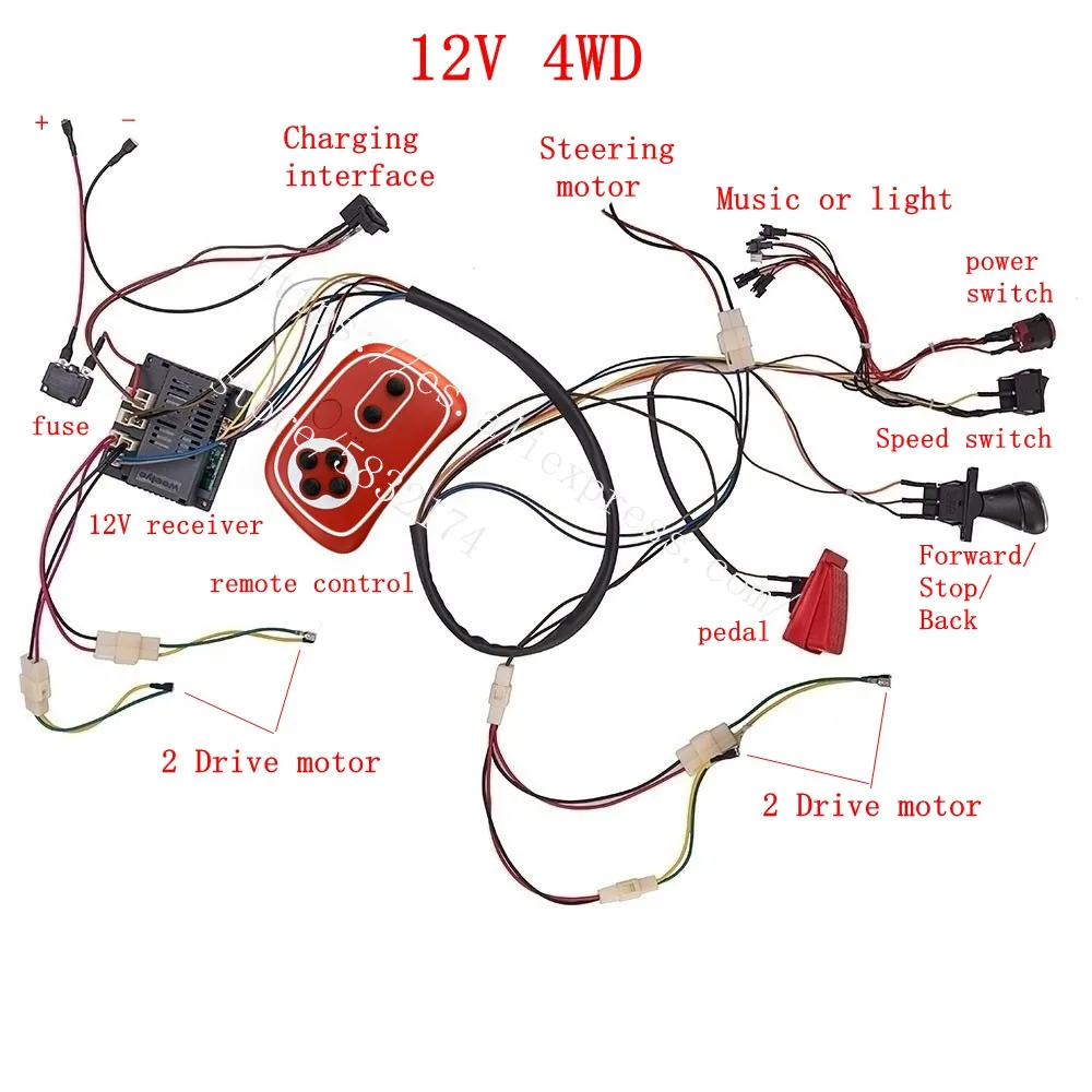
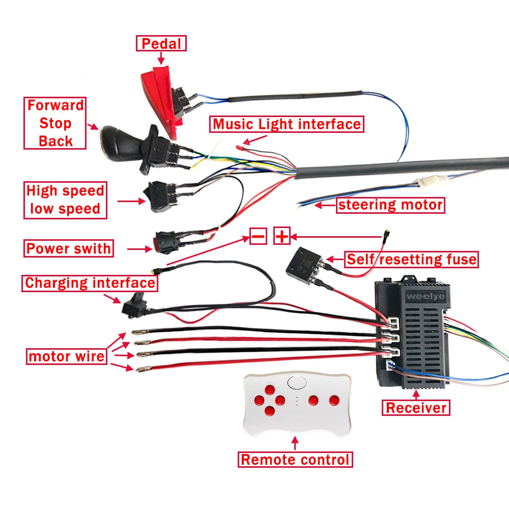
Control switches, including foot pedals and forward-reverse toggle switches, route electrical current through mechanical contacts. Many modern ride-on configurations integrate electromechanical relays or integrated control boards (ICBs) to handle high startup currents, keeping heavy electrical loads away from fragile dash switches. Ground paths—often returning directly to the battery negative terminal via dedicated black wires rather than a metal chassis—complete the loop, ensuring uninterrupted continuity across all connected loads.
[Electric shock and thermal hazards in low-voltage DC toys] — According to consumer product safety surveillance data from the Consumer Product Safety Commission (CPSC), improperly rated replacement batteries or bypassed thermal fuses remain leading contributors to thermal events in motorized children’s ride-on vehicles.
Diagram Explanation and Key Components
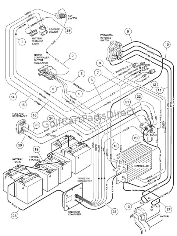
Decoding a 12v kids ride on car wiring diagram requires familiarity with standardized graphic symbols, line types, and color-coding conventions. Schematics use solid lines to represent current-carrying conductors, while dashed lines typically indicate mechanical linkages or internal circuit board pathways. Standard symbols depict batteries as alternating long and short parallel lines, switches as broken conductor paths with movable blades, and motors as circles enclosing the letters “DC.”
Color codes vary by manufacturer and region, though red universally designates positive voltage supply lines, and black or dark blue represents negative returns or ground conductors. Secondary control circuits may utilize yellow, green, or white wires to distinguish between accelerator inputs, steering motor feeds, and radio module power. For more complex setups, technicians frequently reference Vehicle Wiring Diagrams to understand multi-relay switching logic, or consult Relay and Component Wiring Diagrams when isolating distinct control modules from heavy load circuits.
Every component on the schematic serves a distinct operational purpose. The accelerator pedal functions as a normally open momentary switch that closes the primary circuit only when depressed by the operator. The forward-reverse switch acts as a double-pole double-throw (DPDT) reversing polarity switch, which crosses the positive and negative leads feeding the drive motors to reverse the magnetic field orientation and spin the wheels backward. Battery charging ports incorporate a protective diode or relay disconnect switch to prevent the vehicle from moving while plugged into an external wall charger.
Common Problems and Troubleshooting Methods
Systematic fault-finding begins with observing symptoms, such as complete power loss, sluggish motor performance, or non-functional accessories. Technicians approach Wiring Troubleshooting by dividing the network into manageable segments: the power supply, the control circuit, and the final output actuators. Safety comes first; always disconnect the battery before inspecting internal wire harnesses, and use a digital multimeter set to DC voltage and continuity to isolate electrical faults.
Open circuits represent the most frequent failure point, typically caused by loose spade connectors, corroded battery terminals, or broken wire strands inside tight steering pivot points. A high-resistance connection generates localized heat, melting plastic switch housings even if the main fuse remains intact. Short circuits manifest as instantly blown fuses or dead batteries, usually stemming from pinched wires trapped beneath the molded plastic body frame during reassembly. Technicians check continuity across suspected wire segments and verify battery state-of-charge under load, recognizing that a surface voltage reading of 12 volts can collapse instantly to zero if internal battery plates are sulfated.
Practical Tips and Safety Considerations
Executing clean electrical repairs demands proper tools, including ratcheting terminal crimpers, heat-shrink tubing, and marine-grade wire with copper strands for optimal flexibility and corrosion resistance. Splicing wires with electrical tape alone invites moisture ingress and high-resistance faults, especially given that ride-on toys frequently encounter damp grass, mud, and outdoor weather elements. Always match replacement wire gauges to the original manufacturer specifications; undersized wire acts as a resistor, causing voltage drop, sluggish motor speeds, and premature thermal breakdown.
When servicing or modifying these electrical systems, always isolate the power source by physically unplugging the battery harness. Never bridge or bypass thermal fuses with solid copper wire or higher-amp fuses to solve persistent tripping issues, as this removes essential circuit protection and introduces severe fire hazards. For advanced electronic control boards or complex sound and lighting accessories, reviewing supplementary guides such as Appliance and Device Wiring provides additional insight into internal control circuitry and low-power logic routing.
Conclusion
Navigating a 12v kids ride on car wiring diagram empowers technicians and enthusiasts to diagnose faults accurately, restore full operational performance, and maintain high safety standards. By respecting direct current principles, utilizing proper diagnostic tools, and adhering to strict wire sizing and fusing practices, electrical integrity remains uncompromised. Diligent troubleshooting transforms complex wiring challenges into straightforward, manageable repairs, ensuring safe and reliable operation for years to come.
Quick Wiring Specifications & Terminal Guide
| Component / Circuit | Standard Wire Gauge | Recommended Protection |
|---|---|---|
| Control & Trigger Signals | 18 – 20 AWG | 5A – 7.5A Inline Fuse |
| Standard Auxiliary Load | 14 – 16 AWG | 15A – 20A Circuit Breaker |
| Main Power Feed / Supply | 10 – 12 AWG | 30A – 40A Heavy-Duty Relay |
Images References