Introduction
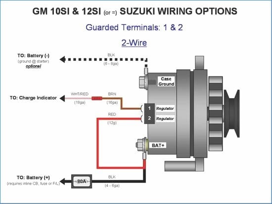
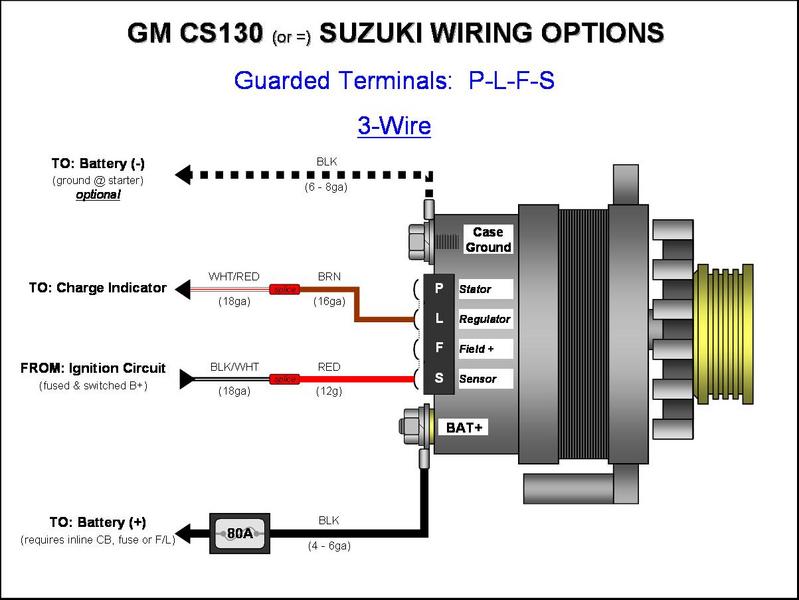
A wireing diagram for 2 wire gm alternator outlines the simplified internal voltage regulation circuit found on many General Motors legacy charging systems, specifically the popular SI-series and early CS-series units. This specific configuration utilizes two distinct external terminal connections—traditionally labeled Terminal 1 and Terminal 2—to control the electromagnetic field inside the generator and sense system voltage. Understanding this setup matters because incorrect terminal wiring or poor circuit resistance leads directly to a dead battery, an uncharged electrical system, or thermal damage to the charging harness. Vehicle restoration enthusiasts, mobile service mechanics, and automotive electrical technicians encounter these dual-terminal layouts frequently when converting older vehicles or troubleshooting chronic voltage drop issues. Properly interpreting these schematics improves installation quality, prevents costly component failure, and ensures the 12-volt DC automotive network operates within safe parameters defined by organizations like the Society of Automotive Engineers (Vehicle Wiring Diagrams).
💡 Technical Key Takeaways:
- Core Focus: Diagnostic schematic and terminal connection layout for Wireing Diagram For 2 Wire Gm Alternator.
- Target Scope: Field technicians, automotive DIYers, and residential/commercial electricians.
- Safety Rule: Always disconnect the primary power source/battery terminal and verify zero voltage with a multimeter before touching wires.
Core Concepts and Wiring Fundamentals
The 2-wire GM alternator system relies on a self-exciting internal voltage regulator that manages battery charging by modulating rotor field current. The first connection, designated as Terminal 1 (often colored brown in standard General Motors harnesses), serves as the ignition feed and indicator lamp circuit. This wire provides a small initial excitation current from the dashboard warning light or a switched 12-volt ignition source to turn on the internal regulator when the key rotates to the run position.
The second connection, designated as Terminal 2 (typically red), functions as the voltage sense circuit. This wire runs directly from the alternator output stud or the main power distribution junction to monitor the actual electrical system voltage under load. By comparing this sensed voltage against an internal reference, the regulator adjusts the magnetic field strength to maintain a steady system output between 13.5 and 14.5 volts while the engine runs.
Heavy power delivery bypasses the two-wire plug entirely and flows through a high-amperage threaded stud labeled output (BAT). This primary battery cable must be sized correctly according to expected current draws and safely routed away from hot exhaust manifolds to prevent catastrophic short circuits. Fuses or fusible links protect this high-output path, while reliable chassis grounds complete the return circuit back to the negative battery terminal.
[Automotive electrical failures, particularly in charging systems and alternators, account for a substantial percentage of roadside breakdowns according to historical roadside assistance data.] — [Consumer Product Safety Commission and automotive industry service reports]
Diagram Explanation and Key Components
Reading a wireing diagram for 2 wire gm alternator requires recognizing specific schematic symbols, standard automotive color codes, and pinout orientations on the plastic connector housing. Schematics typically represent the alternator as a large circle or block with distinct terminal callouts corresponding to physical spade terminals molded into the regulator plug. Technicians must pay close attention to terminal markings, as reversing Terminal 1 and Terminal 2 can prevent the alternator from charging or cause the internal battery drain when the vehicle sits parked overnight.
Standard GM wiring conventions utilize specific color codes for the dual-terminal plug, though aftermarket replacement harnesses sometimes deviate from factory specifications. Terminal 1 connects to the brown indicator lamp wire, which requires a proper resistance bulb or a parallel inline resistor if converted to a modern LED dash cluster. Without adequate resistance on this circuit, the alternator fails to excite properly at startup. Terminal 2 connects via a red wire to a constant 12-volt source, giving the internal regulator a true reading of system voltage independent of ignition switch resistance drops.
The schematic also illustrates the main battery feed wire, which appears as a heavy-gauge line connecting the alternator output stud directly to the starter solenoid or battery positive post. Relay and switching symbols on the diagram indicate how accessory loads interact with the charging loop, helping technicians trace power distribution during advanced Relay and Component Wiring Diagrams analysis.
Common Problems and Troubleshooting Methods
Diagnosing charging system faults using a wireing diagram for 2 wire gm alternator involves a systematic, step-by-step verification of voltage, resistance, and circuit continuity. A common real-world failure point is high electrical resistance in the Terminal 2 sense wire due to corroded crimp terminals or aged fusible links, which tricks the internal regulator into overcharging the battery. Conversely, an open circuit on Terminal 1 prevents the generator from turning on, resulting in a zero-output condition despite a healthy alternator assembly.
The diagnostic process begins with a visual inspection of the wiring harness for melted insulation, loose plug retention clips, or oil contamination. Next, a digital multimeter set to DC volts measures battery voltage with the engine off, followed by a running voltage test across the battery posts. If the system fails to charge, back-probing the connector determines if battery voltage reaches Terminal 2 and if switched voltage reaches Terminal 1 during key-on.
Voltage drop testing across the main battery output cable identifies hidden internal corrosion inside thick copper strands. Technicians isolate faults by checking continuity to ground and verifying that the alternator housing maintains a clean, unpainted metallic connection to the engine block (Wiring Troubleshooting).
Practical Tips and Safety Considerations
Automotive electrical work demands strict adherence to safety protocols, particularly when handling high-amperage circuits directly connected to the vehicle battery. Before servicing any alternator wiring, disconnect the negative battery cable to prevent accidental arcing, tool welding, or sudden electrical shock. Technicians must always wear safety glasses and remove metallic jewelry when working near rotating belts and live power distribution studs.
When repairing damaged pigtail connectors, use high-temperature automotive-grade cross-linked polyethylene wire rather than standard household wire, which degrades rapidly under hood temperatures. Ensure all soldered joints or crimped connections receive proper heat shrink tubing with adhesive lining to seal out moisture and road salt. Avoid running charging wires near sharp sheet metal edges or moving steering shafts; secure every harness with insulated P-clamps or high-strength nylon zip ties.
Conclusion
Mastering the wireing diagram for 2 wire gm alternator empowers DIY enthusiasts and professional technicians to diagnose and repair classic charging faults with confidence. By understanding the distinct roles of the excitation circuit, the voltage sensing line, and the high-output power stud, operators can eliminate guesswork and prevent recurring electrical failures. Careful attention to wire gauge selection, terminal cleanliness, and proper schematic interpretation ensures long-term reliability for any 12-volt automotive electrical system.
Quick Wiring Specifications & Terminal Guide
| Component / Circuit | Standard Wire Gauge | Recommended Protection |
|---|---|---|
| Control & Trigger Signals | 18 – 20 AWG | 5A – 7.5A Inline Fuse |
| Standard Auxiliary Load | 14 – 16 AWG | 15A – 20A Circuit Breaker |
| Main Power Feed / Supply | 10 – 12 AWG | 30A – 40A Heavy-Duty Relay |
Images References