Introduction
A starter solenoid relay motorcycle wiring diagram is a visual schematic that maps out the electrical pathways between the battery, ignition switch, starter relay, and starter motor on a two-wheeled vehicle. Understanding this schematic matters because motorcycles operate in harsh environments where vibration, moisture, and thermal cycling frequently compromise electrical integrity. This documentation is used across the United States, United Kingdom, Canada, and Australia by mechanics and enthusiasts to diagnose no-start conditions, install aftermarket accessories, or restore vintage machines. Proper comprehension of these diagrams directly improves safety, prevents costly component damage, and ensures precise troubleshooting accuracy during diagnostic procedures.
💡 Technical Key Takeaways:
- Core Focus: Diagnostic schematic and terminal connection layout for Starter Solenoid Relay Motorcycle Wiring Diagram.
- Target Scope: Field technicians, automotive DIYers, and residential/commercial electricians.
- Safety Rule: Always disconnect the primary power source/battery terminal and verify zero voltage with a multimeter before touching wires.
Core Concepts and Wiring Fundamentals
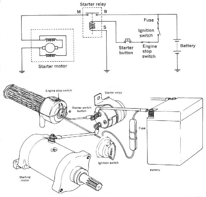
The motorcycle starting system relies on a dual-circuit architecture: a low-current control circuit and a high-current load circuit. The control circuit originates at the battery, flows through the main fuse, passes the ignition switch and engine stop switch, travels through the clutch or neutral safety switch, and finally energizes the starter relay coil. When the start button is depressed, a small electrical current flows through this coil, creating a magnetic field that closes an internal physical switch. This fundamental principle aligns with standard automotive electrical practices governed by the Society of Automotive Engineers (SAE).
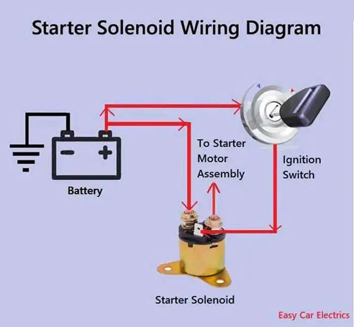
Once the internal relay switch closes, the high-current load circuit engages. Thick-gauge battery cables transfer raw, unfiltered amperage directly from the positive battery terminal through the heavy relay contacts and into the starter motor. The circuit is completed through the metallic chassis ground back to the negative battery terminal. Because the starter motor demands hundreds of amperes during cranking, any high-resistance connection in this path will generate excessive heat and voltage drop. Technicians frequently explore resources like Relay and Component Wiring Diagrams to understand how low-power switches safely govern high-amperage loads.
High-Current Load Warning — According to industry standards published by the Society of Automotive Engineers (SAE), starter circuits routinely draw between 100 to 300 amperes depending on engine displacement, requiring heavy-gauge copper cabling to prevent thermal overload.
Diagram Explanation and Key Components
Reading a starter solenoid relay motorcycle wiring diagram requires familiarity with standardized schematic symbols and regional variations. Lines represent copper conductors, while zigzag patterns indicate fusible links or resistors, and open-switch symbols depict the starter button and safety interlocks. Color coding varies by manufacturer and geography; for instance, Japanese motorcycles often utilize solid green for grounds and red for constant battery power, whereas European models may follow DIN color standards where brown represents ground. Every wiring schematic breaks down into distinct functional zones: power distribution, control switching, and mechanical actuation.
The primary components identified on the schematic include the battery, main fuse, starter relay (often integrated with the main fuse holder), starter motor, and safety switches. The relay itself typically features four terminals: two small control wires for the coil and two large stud terminals for the heavy battery and starter cables. Master technicians often cross-reference complex chassis schematics with Vehicle Wiring Diagrams to trace how the starting circuit integrates with charging and lighting systems. Grasping these visual representations allows technicians to quickly isolate whether a fault originates in the handlebar switch or the power relay itself.
Common Problems and Troubleshooting Methods
Systematic diagnostic procedures for motorcycle starting circuits begin with verifying battery state-of-charge and inspecting main fuse integrity before testing individual components. A classic real-world observation in motorcycle repair is the rapid clicking sound of a starter relay, which typically indicates low battery voltage or a poor ground connection that cannot sustain the electromagnetic coil’s magnetic field. Other frequent failure points include corroded relay terminals, fused contacts inside the solenoid, and fractured wires within the handlebar switch assembly due to steering head movement.
Diagnosis requires a digital multimeter set to measure DC voltage and resistance. Technicians test voltage drop across the heavy relay terminals while attempting to crank the engine, looking for any reading exceeding fractional volts under load. Safety interlock switches, such as the side stand switch or clutch switch, represent another major troubleshooting hurdle; an open safety switch will prevent voltage from reaching the relay coil entirely. For broader fault-finding strategies applicable across different electrical systems, professionals rely on guidance found within Wiring Troubleshooting guides.
Practical Tips and Safety Considerations
High-amperage automotive and motorcycle electrical work demands strict adherence to safety protocols to prevent severe burns, electrical shocks, or accidental vehicle movement. Always disconnect the negative battery terminal before unbolting heavy cables from the starter relay to prevent accidental short circuits against the frame. When replacing damaged wiring harness sections, use automotive-grade cross-linked polyethylene wire and proper crimp-seal connectors protected by marine-grade heat shrink tubing to withstand moisture and vibration. Regional standards such as NFPA 70 (NEC) in the United States, the Canadian Electrical Code (CEC), BS 7671 in the United Kingdom, and AS/NZS 3000 in Australia dictate electrical safety principles, though automotive applications prioritize SAE and ISO standards.
A common beginner mistake is replacing a blown main fuse with a higher-amperage rating when the original fuse fails. This practice eliminates the circuit’s thermal protection and can melt the entire wiring harness. Always verify the exact fuse rating specified by the manufacturer. Ensuring proper routing away from hot exhaust headers and moving steering components prevents future chafing and intermittent electrical faults.
Conclusion
Mastering a starter solenoid relay motorcycle wiring diagram transforms frustrating electrical diagnostics into a logical, methodical process. By separating the low-current control side from the high-current load side, technicians can accurately pinpoint where voltage fails or where excessive resistance develops. Diligent adherence to safety practices, correct wire sizing, and systematic multimeter testing ensure long-term reliability for any motorcycle electrical repair. For further reference on schematics outside the starting system, consult Wiring Diagram Basics to expand foundational electrical knowledge.
Quick Wiring Specifications & Terminal Guide
| Component / Circuit | Standard Wire Gauge | Recommended Protection |
|---|---|---|
| Control & Trigger Signals | 18 – 20 AWG | 5A – 7.5A Inline Fuse |
| Standard Auxiliary Load | 14 – 16 AWG | 15A – 20A Circuit Breaker |
| Main Power Feed / Supply | 10 – 12 AWG | 30A – 40A Heavy-Duty Relay |
Images References