Introduction
A layout diagram for outdoor lighting wiring serves as a master blueprint for planning, installing, and servicing exterior illumination systems. Exterior illumination projects require meticulous coordination of electrical loads, physical routes, and environmental protections to prevent premature failure. Mastering these schematics ensures that installations meet local regulatory standards while optimizing voltage drop management across long runs. Technicians and DIY enthusiasts utilize these visual guides to bridge the gap between architectural lighting design and physical hardware placement. Proper spatial mapping directly enhances circuit safety, simplifies future Wiring Troubleshooting, and guarantees reliable operation through harsh seasonal weather.
💡 Technical Key Takeaways:
- Core Focus: Diagnostic schematic and terminal connection layout for Layout Diagram For Outdoor Lighting Wiring.
- Target Scope: Field technicians, automotive DIYers, and residential/commercial electricians.
- Safety Rule: Always disconnect the primary power source/battery terminal and verify zero voltage with a multimeter before touching wires.
Core Concepts and Wiring Fundamentals
Outdoor lighting installations typically operate on either low-voltage direct current (12V or 24V DC) supplied through a step-down transformer or line-voltage alternating current (120V in North America, 230V in the UK, Europe, and Australia). Low-voltage systems utilize a magnetic or electronic transformer to step down household mains electricity, drastically reducing the risk of shock in wet environments. Line-voltage systems draw power directly from the main distribution panel, requiring rigid conduit burial depths and weatherproof enclosures.
Conductor sizing remains a critical factor in exterior circuits due to extended cable runs. Voltage drop—the reduction in electrical potential along a conductor—occurs naturally over distance, leading to dim lamps or failing drivers if wire gauges are too small. Technicians select heavy-gauge copper cables, such as 10 AWG or 12 AWG for low-voltage setups, to maintain optimal operating voltage at the final fixture of a daisy-chain or hub layout.
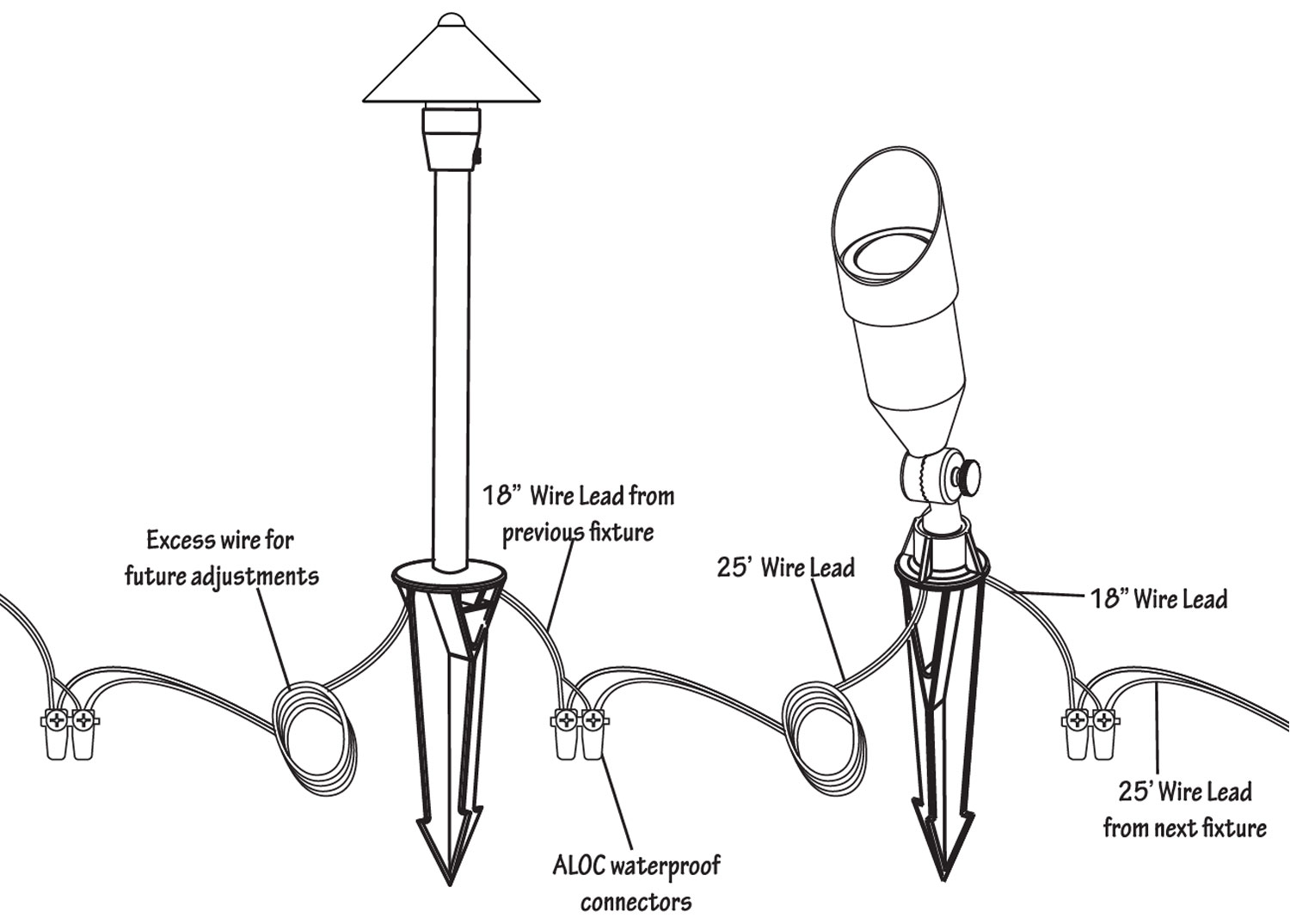
Corrosion is the primary enemy of outdoor electrical integrity. Every splice, junction box, and luminaire connection must employ waterproof wire nuts, gel-filled connectors, or heat-shrink tubing lined with adhesive. Unprotected copper exposed to moisture and soil acidity rapidly oxidizes, creating high-resistance faults that generate heat and interrupt circuit continuity.
[Outdoor electrical safety] — The Electrical Safety Foundation International (ESFI) notes that underground utility strikes and improper exterior wiring methods account for a significant percentage of preventable residential electrical injuries and property damage annually.
Diagram Explanation and Key Components
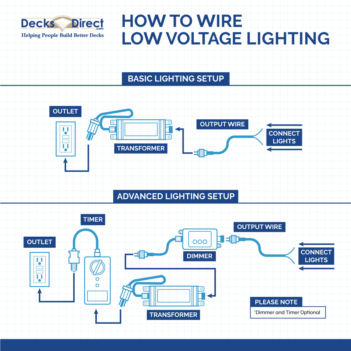
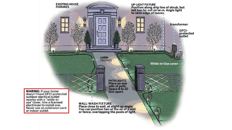
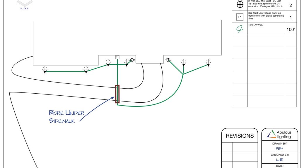
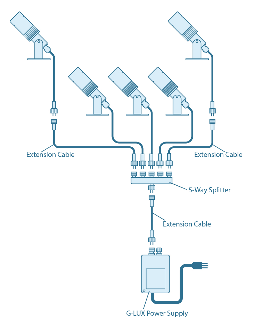
Reading a layout diagram for outdoor lighting wiring requires familiarity with standardized schematic symbols representing transformers, photocells, motion sensors, drivers, and luminaires. A standard layout typically displays a bird-eye view of the property, charting the physical path of direct-burial cables from a central power source to individual landscape fixtures.
Line types differentiate power delivery methods: solid lines usually denote trench-laid cables, dashed lines indicate overhead spans, and specialized symbols mark junction locations. Color coding on schematics helps identify polarity and circuit function. In North America under the National Electrical Code (NEC) or Canadian Electrical Code (CEC), low-voltage wires are often unsheathed multi-strand copper, whereas line-voltage layouts follow standard hot (black/red), neutral (white), and ground (green/bare) conventions. Conversely, in the UK (BS 7671) and Australia (AS/NZS 3000), line-voltage circuits utilize brown (active), blue (neutral), and green-and-yellow (protective earth) conductors.
Control devices appear on the diagram as interrupters along the feed line. Astronomical timers, photocells, and motion detectors dictate when the circuit energizes, preventing manual operation and optimizing energy usage. Reviewing these schematics alongside Home Electrical Wiring Diagrams helps clarify how exterior sub-panels tie into the main service entrance.
Common Problems and Troubleshooting Methods
Exterior lighting faults generally manifest as complete system blackouts, flickering fixtures, or intermittently tripped circuit breakers and ground fault circuit interrupters (GFCIs). Diagnosing these issues demands a systematic, methodical approach starting at the power source and moving toward the end of the line.
When an entire low-voltage zone fails, testing begins at the transformer output terminals using a digital multimeter set to alternating or direct current, depending on the unit type. If output voltage reads zero or drops significantly under load, the internal fuse or circuit breaker on the transformer requires inspection. A tripped breaker often points to a downstream short circuit caused by damaged cable insulation or water ingress inside a fixture housing.
For line-voltage systems, a tripped GFCI indicates a ground fault where current leaks to the earth path due to moisture accumulation. Technicians isolate sections of the run by disconnecting branch circuits sequentially until the GFCI holds. For further insight into control logic failures, consulting Relay and Component Wiring Diagrams assists in verifying proper switching operations for automated lighting arrays.
Practical Tips and Safety Considerations
Mains-voltage outdoor wiring presents severe shock and electrocution hazards, especially in damp earth or standing water. Before performing any physical installation, modification, or diagnostic testing on line-voltage systems, technicians must de-energize the circuit at the main breaker panel and verify zero energy state using a reliable voltage tester. Local regulations in the US, UK, Canada, and Australia frequently mandate that permanent 120V/230V exterior wiring be installed by a licensed electrician.
Trenching depth is another vital physical consideration. Protective conduit must be buried at depths specified by regional codes to prevent accidental puncture from gardening tools, lawn aerators, or shifting soil. When utilizing direct-burial cable without conduit, backfilling with clean sand before adding soil protects the outer sheath from sharp rocks.
A frequent installation error involves overloading a single low-voltage transformer tap. Calculating the total wattage of all lamps on a single circuit and ensuring it remains below eighty percent of the transformer’s maximum rated capacity prevents thermal overload and premature transformer burnout.
Conclusion
Executing an exterior illumination project safely and efficiently relies entirely on accurate planning and adherence to established electrical principles. Utilizing a detailed layout diagram for outdoor lighting wiring eliminates guesswork, minimizes voltage drop, and ensures compliance with regional safety codes. By respecting the challenges of moisture, soil movement, and electrical loads, installers create robust, long-lasting systems that enhance property aesthetics and security. Proper documentation and methodical troubleshooting remain the foundation of professional electrical craftsmanship.
Quick Wiring Specifications & Terminal Guide
| Component / Circuit | Standard Wire Gauge | Recommended Protection |
|---|---|---|
| Control & Trigger Signals | 18 – 20 AWG | 5A – 7.5A Inline Fuse |
| Standard Auxiliary Load | 14 – 16 AWG | 15A – 20A Circuit Breaker |
| Main Power Feed / Supply | 10 – 12 AWG | 30A – 40A Heavy-Duty Relay |
Images References