Introduction
Learning how to connect 4pin relay to starter is an essential skill for automotive technicians and DIY mechanics dealing with high-current cranking circuits. A starter motor draws massive electrical loads, often exceeding two hundred amperes during engine cranking. Running this heavy current directly through a standard ignition switch causes premature switch failure, burned contacts, and severe voltage drop. Integrating an electromagnetic switching device, commonly known as a relay, isolates the delicate dashboard control circuit from the high-amperage demands of the starter solenoid. This setup is frequently utilized in custom engine swaps, race vehicle builds, and troubleshooting older machinery suffering from intermittent hot-start issues. Understanding this configuration improves circuit reliability, protects sensitive electronic ignition components, and ensures accurate electrical diagnosis across 12-volt and 24-volt direct current (DC) automotive architectures. Additional schematics and related configurations can be found within the Vehicle Wiring Diagrams archives.
💡 Technical Key Takeaways:
- Core Focus: Diagnostic schematic and terminal connection layout for How To Connect 4Pin Relay To Starter.
- Target Scope: Field technicians, automotive DIYers, and residential/commercial electricians.
- Safety Rule: Always disconnect the primary power source/battery terminal and verify zero voltage with a multimeter before touching wires.
Core Concepts and Wiring Fundamentals
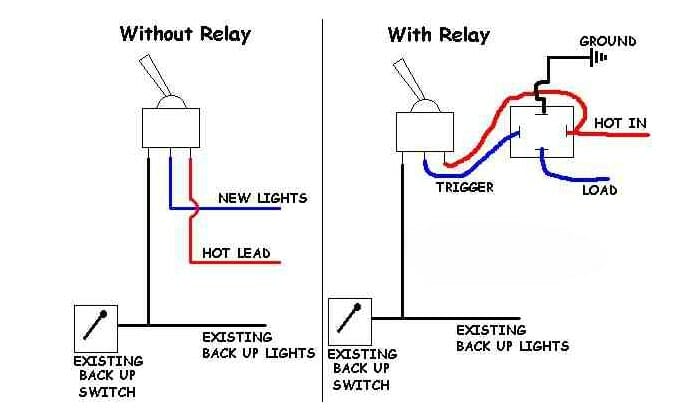
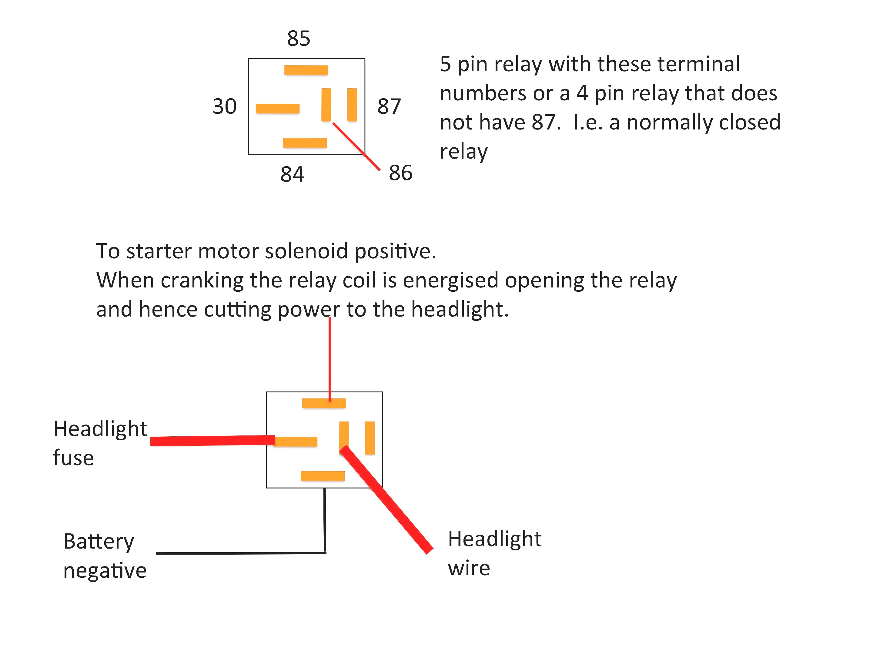
A standard automotive relay operates as an electrically operated switch utilizing a low-power control circuit to manage a high-power load circuit. The device features four primary terminals, universally standardized by the Society of Automotive Engineers (SAE) and DIN standards. Pin 30 receives constant power directly from the battery via a heavy-gauge fusible link or inline circuit protection device. Pin 87 connects directly to the starter solenoid control terminal, delivering the high current required to engage the starter motor. Pin 85 serves as the ground path for the internal electromagnetic coil, while pin 86 receives the switched ignition signal from the key switch or push-button starter. When the ignition switch closes, voltage energizes the coil across pins 85 and 86, creating a magnetic field that pulls an internal metal contact closed. This physical closure bridges pin 30 to pin 87, allowing heavy current to flow directly to the starter solenoid without taxing the dashboard wiring. Selecting the correct wire gauge is critical for this setup; heavy-gauge copper wiring, typically American Wire Gauge (AWG) 10 or 8, must be used for the high-current loop between the battery, relay, and starter. Meanwhile, lighter-gauge wire such as AWG 16 or 18 is sufficient for the trigger circuit running from the ignition switch to the relay coil. Regional differences play a distinct role in automotive restoration and repair. While North American vehicles rely heavily on standard SAE wire color designations, vehicles manufactured in the United Kingdom or Australia often follow BS standards or specific manufacturer color coding. Furthermore, local electrical work on modified vehicles should always align with recognized automotive electrical practices outlined by organizations like the SAE. Mechanics must also disconnect the negative battery terminal before initiating any physical wiring modifications to prevent accidental short circuits or arc flashes.
[Finding] — The Society of Automotive Engineers (SAE) establishes standardized terminal numbering conventions for automotive relays to ensure universal compatibility and safe circuit integration across global vehicle manufacturing sectors.
Diagram Explanation and Key Components
Reading a schematic for how to connect 4pin relay to starter requires a solid grasp of standard automotive symbols, line types, and terminal designations. On a typical blueprint or wire routing diagram, thin lines represent low-current control wires, while thick lines indicate high-amperage power paths. The relay itself is drawn as a box containing an open switch contact and a dashed or solid line representing the electromagnetic coil. Terminal numbers 30, 87, 86, and 85 are printed adjacent to their respective connection points on the relay body and the schematic symbol. Tracing the diagram reveals the complete loop: power originates at the positive battery post, travels through a heavy-gauge cable to a dedicated fuse holder, and terminates at relay pin 30. From relay pin 87, a separate heavy-gauge conductor runs forward to the starter motor’s starter solenoid trigger spade. The control side is equally straightforward, originating at the ignition switch or starter relay output, feeding pin 86, while pin 85 runs to a clean, unpainted chassis ground. In practice, missing a solid ground connection at pin 85 is one of the most frequent errors made during custom installations, preventing the electromagnetic coil from energizing entirely. Technicians utilize digital multimeters set to continuity or resistance modes to verify that pin 85 possesses a direct path to the vehicle frame before applying power. For a broader understanding of how these schematic symbols translate across different systems, reviewing Wiring Diagram Basics provides invaluable foundational knowledge.
Common Problems and Troubleshooting Methods
Systematic fault-finding when dealing with a starter relay circuit requires isolating the control side from the load side to pinpoint the exact failure point. A common symptom is a faint clicking noise from the relay housing when the key is turned, which typically indicates that the control circuit is functioning, but the high-current load side or the starter solenoid itself is failing to draw proper current. Conversely, a complete lack of sound usually points to an open circuit in the trigger wire, a blown fuse, or a faulty ground at pin 85. Technicians begin diagnostic procedures by checking battery voltage at pin 30 using a digital multimeter; this reading should match battery voltage under no-load conditions. Next, the ignition switch is engaged while monitoring voltage at pin 86 to ensure the trigger signal reaches the coil. If voltage is present at both input pins, but the starter does not crank and no continuity is measured between pins 30 and 87 during activation, the internal relay contacts have pitted or welded shut, requiring immediate component replacement. Another frequent failure point involves high resistance at the relay socket terminals due to moisture intrusion, corrosion, or heat degradation from high electrical loads. Cleaning terminal blades with electrical contact cleaner and applying dielectric grease prevents recurring connection failures in harsh under-hood environments. When electrical faults extend beyond the starting system into complex auxiliary circuits, consulting Wiring Troubleshooting guides helps streamline the diagnostic process.
Practical Tips and Safety Considerations
Executing a reliable installation demands strict adherence to professional mechanical standards, proper insulation techniques, and robust mechanical fastening. Always mount the relay with the terminal blades facing downward or sideways to prevent moisture, oil, and road debris from pooling inside the connector socket. Secure the relay body securely to the inner fender or firewall using mechanical fasteners rather than relying solely on zip ties, as continuous engine vibration can fracture solder joints or loosen wire crimps. Every high-current connection must be protected with heat-shrink tubing featuring adhesive linings to seal out corrosive elements and prevent accidental shorts against the chassis. Over-fusing is a dangerous mistake; the inline fuse protecting the wire feeding pin 30 must be rated according to the ampacity of the wire gauge used, rather than the maximum draw of the starter solenoid. Never bypass fuses or circuit protection devices during troubleshooting phases, as starter circuits are capable of delivering destructive levels of current that can easily melt wire harnesses and start electrical fires. Technicians must always verify that the vehicle transmission is in park or neutral and the parking brake is firmly engaged before testing any starter modification. Following these established field practices ensures long-term system stability and protects both the technician and the vehicle from catastrophic electrical damage.
Conclusion
Mastering how to connect 4pin relay to starter safeguards delicate ignition switches while delivering the high amperage necessary for reliable engine cranking. By carefully separating the low-current trigger circuit from the heavy-duty power loop, technicians create a durable, professional-grade electrical modification that withstands the rigors of daily automotive operation. Proper wire sizing, secure terminal crimps, clean chassis grounds, and correct fuse placement form the backbone of any successful installation. Systematic testing with a multimeter remains the most effective method for diagnosing faults and verifying circuit integrity before placing a vehicle back into service. Prioritizing safety, cleanliness, and adherence to established electrical standards ensures reliable performance for years to come. Additional component layouts and relay configurations are available within the Relay and Component Wiring Diagrams directory.
Quick Wiring Specifications & Terminal Guide
| Component / Circuit | Standard Wire Gauge | Recommended Protection |
|---|---|---|
| Control & Trigger Signals | 18 – 20 AWG | 5A – 7.5A Inline Fuse |
| Standard Auxiliary Load | 14 – 16 AWG | 15A – 20A Circuit Breaker |
| Main Power Feed / Supply | 10 – 12 AWG | 30A – 40A Heavy-Duty Relay |
Images References