Introduction
Alternator Delco-Remy wiring governs the electrical connections for one of the most prolific charging system architectures found in automotive, marine, and industrial internal combustion engines. Delco-Remy charging units, originating from General Motors and utilized broadly across global manufacturing, rely on specific terminal layouts to regulate system voltage, energize internal magnetic fields, and communicate charging status to dashboard indicators. Grasping this circuitry matters because incorrect terminal connections instantly destroy internal voltage regulators or drain batteries through unswitched parasitic loads. Such configurations appear universally in older classic vehicles, heavy-duty commercial trucks, agricultural equipment, and custom engine retrofits globally. Understanding these circuits improves installation quality, prevents costly electrical fires, and ensures accurate diagnostic results when evaluating charging system failures.
💡 Technical Key Takeaways:
- Core Focus: Diagnostic schematic and terminal connection layout for Alternator Delco-Remy Wiring.
- Target Scope: Field technicians, automotive DIYers, and residential/commercial electricians.
- Safety Rule: Always disconnect the primary power source/battery terminal and verify zero voltage with a multimeter before touching wires.
Core Concepts and Wiring Fundamentals
Delco-Remy charging systems operate on 12V or 24V direct current (DC) topologies, typically centered around internal or external voltage regulation depending on the specific model generation, such as the classic 10SI, 12SI, or modern high-output series. The architecture relies on heavy-gauge power feeds, ignition-switched excitation lines, and sensing circuits that monitor battery voltage directly to dictate alternator output. Heavy copper cables deliver the generated current from the main output stud directly to the battery positive terminal or starter solenoid junction, carrying the full electrical load of the vehicle.
Control circuits utilize lower-gauge wiring to manage magnetic field excitation and voltage sensing. The ignition switch provides a low-amperage reference signal through a warning indicator lamp or resistor wire to wake up the internal electronics. Fuses and fusible links protect these secondary circuits from unexpected overloads. Ground paths remain critically important; the alternator housing must maintain a clean, zero-resistance metallic connection to the engine block and chassis to complete the return path for high-amperage charging currents.
[Finding] — According to automotive electrical safety studies cited by the Society of Automotive Engineers (SAE), oxidized or loose alternator ground connections account for a significant percentage of premature voltage regulator failures.
Diagram Explanation and Key Components
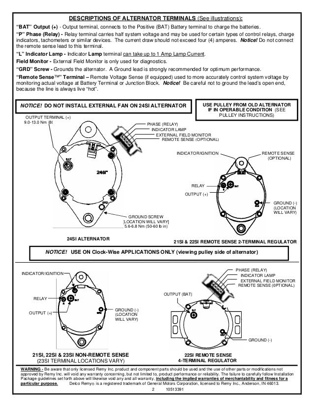
Reading electrical schematics for alternator delco-remy wiring requires identifying standardized terminal designations stamped directly onto the rear housing or plastic connector plug. The primary output stud is universally labeled BAT, standing for battery, and connects via heavy-gauge cable to the power distribution center. The excitation terminal, frequently marked as the #1 terminal or designated with the letter R or I, handles the initial turn-on signal from the ignition circuit. The voltage sensing terminal, marked as the #2 terminal or S, monitors system voltage away from the charging stud to compensate for line voltage drops.
Schematics illustrate these connections using standardized lines representing conductors, with specific line weights distinguishing high-current charging paths from low-current control signals. Color codes vary by region and manufacturer—such as red for main battery feeds and brown for indicator lamp circuits—requiring technicians to cross-reference factory service manuals or Vehicle Wiring Diagrams for exact specifications. Symbols on the diagram denote diodes, windings, and external fusible links, mapping out how mechanical rotation translates into regulated electrical energy.
Common Problems and Troubleshooting Methods
Systematic diagnostic testing for alternator delco-remy wiring isolates faults between the charging unit, wiring harness, battery, and electronic control modules. Typical failures manifest as undercharging, overcharging, battery drain while the vehicle sits parked, or flickering dashboard warning lamps. Technicians begin diagnosis by performing a visual inspection of all terminal connections, checking for corrosion, thermal discoloration, or loose mechanical fasteners.
A structured diagnostic workflow utilizes a digital multimeter to measure voltage drops across individual wires and connections under active electrical load. The diagnostic process verifies that battery voltage increases to appropriate charging levels while the engine runs, confirms continuity on the ignition excitation wire, and checks for excessive resistance on both the positive output cable and the chassis ground path. Technicians must disconnect the negative battery cable before servicing any high-current wiring connections to prevent accidental arcing or component damage. Diagnostic procedures should always be treated as a method of identifying faults rather than a guaranteed cure for mechanical wear inside the alternator.
Practical Tips and Safety Considerations
Successful installation of Delco-Remy charging circuits demands strict adherence to proper wire sizing, secure mechanical crimps, and high-temperature insulation rated for under-hood environments. Undersized cables on the main BAT output terminal introduce high resistance, generating excessive heat and reducing overall charging efficiency. Technicians must route wires away from exhaust manifolds, moving belts, and sharp sheet metal edges, securing harnesses with insulated clamps and protective split-loom tubing.
Safety remains paramount when working around automotive electrical systems, where high-amperage batteries can deliver severe burns or spark unintended fires. Always disconnect the battery ground before servicing alternators or modifying wiring harnesses. Adhere strictly to regional electrical standards, such as those outlined by the Wiring Diagram Basics guides, and consult a qualified technician when local regulations or complex multi-battery setups require advanced electrical expertise.
Conclusion
Mastering alternator delco-remy wiring empowers technicians and hobbyists to maintain, diagnose, and repair charging systems with confidence and precision. Respecting terminal designations, maintaining pristine ground paths, and using correct wire gauges ensure long-term electrical reliability across diverse automotive and industrial platforms. For further exploration of related electrical architectures, consult resources on Relay and Component Wiring Diagrams to expand diagnostic proficiency.
Quick Wiring Specifications & Terminal Guide
| Component / Circuit | Standard Wire Gauge | Recommended Protection |
|---|---|---|
| Control & Trigger Signals | 18 – 20 AWG | 5A – 7.5A Inline Fuse |
| Standard Auxiliary Load | 14 – 16 AWG | 15A – 20A Circuit Breaker |
| Main Power Feed / Supply | 10 – 12 AWG | 30A – 40A Heavy-Duty Relay |
Images References




