Introduction
Understanding what is an alternator exciter wire is essential for diagnosing charging system failures in 12V and 24V automotive and heavy-duty electrical architectures. This specific conductor delivers initial voltage to the rotor field windings, waking up the internal voltage regulator so the alternator can begin producing output current once the engine reaches running speed. Without this initial signal, modern charging units remain dormant, leaving the vehicle entirely dependent on battery power until depletion. Grasping the underlying circuit topology improves troubleshooting accuracy, prevents unnecessary alternator replacements, and ensures safe diagnostic practices across diverse vehicle platforms.
💡 Technical Key Takeaways:
- Core Focus: Diagnostic schematic and terminal connection layout for What Is An Alternator Exciter Wire.
- Target Scope: Field technicians, automotive DIYers, and residential/commercial electricians.
- Safety Rule: Always disconnect the primary power source/battery terminal and verify zero voltage with a multimeter before touching wires.
Core Concepts and Wiring Fundamentals
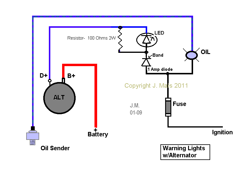
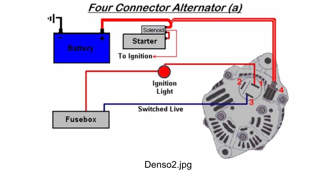
The alternator exciter wire operates within the primary control circuit of a charging system, bridging the ignition switch, the dashboard charge indicator lamp, and the voltage regulator. When the ignition key turns to the run position, battery voltage travels through the indicator lamp or a dedicated series resistor down to the exciter terminal, typically designated as terminal L, D+, or IGN depending on the manufacturer. This low-amperage current magnetizes the rotor core, creating the initial magnetic field required for electromagnetic induction when the pulley spins.
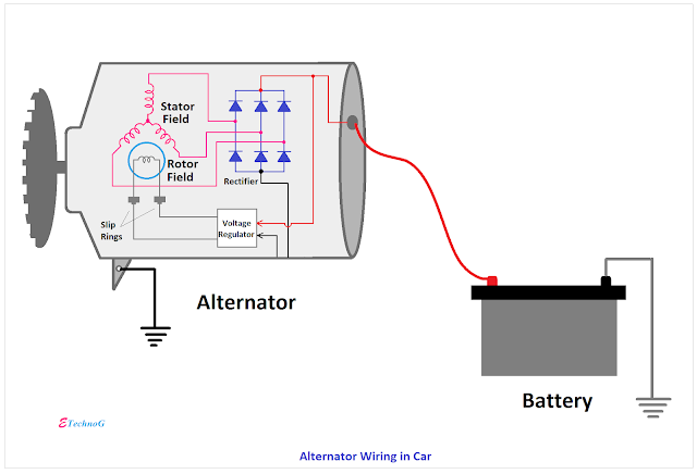
Once the alternator spins and begins generating its own power through internal stator windings and diode rectifiers, voltage at the output terminal matches or exceeds the excitation voltage. At this threshold, the voltage regulator equalizes the potential difference across the exciter circuit, extinguishing the dashboard warning light. In many modern Powertrain Control Module (PCM) controlled charging systems, this wire functions as a bidirectional data or pulse-width modulated (PWM) duty-cycle line rather than a simple on-and-off switched power feed, communicating load demands and diagnostic fault codes directly to the engine computer.
Society of Automotive Engineers (SAE) J1818 — Establishes standard terminal designations and performance test procedures for automotive electrical charging systems, including excitation circuit parameters.
Diagram Explanation and Key Components
Reading a schematic involving what is an alternator exciter wire requires identifying standardized symbols for the ignition switch, fuse panels, warning indicators, and multi-pin regulator connectors. On a typical Vehicle Wiring Diagrams resource, the exciter circuit appears as a thin-gauge conductor—often colored brown with a tracer line in European applications or light green in many North American vehicles—running from the instrument cluster to the alternator plug. Dotted lines on these schematics frequently denote internal alternator components, such as the brush assembly, slip rings, and integrated circuit regulator.
Reviewing Relay and Component Wiring Diagrams helps technicians understand how auxiliary ignition relays may supply power to the exciter circuit on heavy machinery or customized electrical setups. The diagram symbols clarify whether the circuit relies on a physical incandescent dash bulb for necessary baseline resistance or utilizes a solid-state resistor block. Misinterpreting these symbols during custom swaps often results in charging failures, as LEDs substituted for standard dash bulbs fail to provide adequate current draw for older regulator designs.
Common Problems and Troubleshooting Methods
Diagnosing faults related to what is an alternator exciter wire involves a systematic voltage-drop and continuity testing procedure to isolate breaks, high-resistance connections, or grounded harnesses. A frequent real-world failure point occurs where the thin exciter wire enters the main engine harness near high-heat exhaust manifolds, causing insulation degradation and internal copper corrosion. Technicians must always disconnect the negative battery cable before inspecting or probing sensitive electronic circuits to prevent accidental short circuits against grounded vehicle chassis components.
Begin the diagnostic process by verifying battery voltage with the engine off, then switch the ignition to the run position without starting the engine and check for voltage at the disconnected alternator exciter terminal. The presence of battery voltage—or a slight voltage drop across a lit dashboard bulb—confirms the supply side is functional. If voltage is absent, trace backward through the fuse panel and ignition switch following structured guidelines found in professional Wiring Troubleshooting procedures. If voltage is present at the connector yet the alternator fails to charge upon startup, the internal regulator or brushes require replacement.
Practical Tips and Safety Considerations
Working safely around automotive electrical systems requires strict adherence to standard workshop protocols, including wearing eye protection and removing metallic jewelry to prevent arc flashes. When repairing a damaged exciter wire, technicians should use marine-grade heat-shrink butt connectors and proper crimping tools rather than twisting wires together, as high engine bay vibrations quickly fatigue substandard splices. Ensuring correct wire gauge sizing—usually matching the original cross-sectional area, typically 0.5mm² to 1.0mm²—maintains precise circuit resistance and prevents erratic voltage regulation.
A common mistake during alternator replacement is forcing brittle plastic connector locks, which breaks the locking tab and leads to intermittent exciter contact over rough terrain. Applying a small amount of dielectric grease to the connector terminals seals out moisture and road salt, mitigating future corrosion risks. Always verify that battery disconnection procedures comply with manufacturer specifications to avoid disrupting adaptive memory modules or anti-theft systems during physical repairs.
Conclusion
Mastering the function and testing of what is an alternator exciter wire empowers technicians and DIY mechanics to resolve complex charging system malfunctions efficiently. By combining accurate schematic interpretation with methodical diagnostic testing, practitioners can accurately isolate wiring faults from actual alternator hardware failures. Proper repair techniques and adherence to safety standards guarantee long-term reliability and protect sensitive electronic control units from voltage spikes. For further exploration of related electrical architectures, consult comprehensive resources on Wiring Diagram Basics.
Quick Wiring Specifications & Terminal Guide
| Component / Circuit | Standard Wire Gauge | Recommended Protection |
|---|---|---|
| Control & Trigger Signals | 18 – 20 AWG | 5A – 7.5A Inline Fuse |
| Standard Auxiliary Load | 14 – 16 AWG | 15A – 20A Circuit Breaker |
| Main Power Feed / Supply | 10 – 12 AWG | 30A – 40A Heavy-Duty Relay |
Images References