Introduction
A pressure switch wiring diagram refrigeration layout maps the electrical connections for safety and control devices that monitor refrigerant pressure within commercial and residential cooling systems. Interpreting these schematics matters because pressure switches protect compressors from catastrophic failure caused by excessive head pressure or a complete loss of charge. These control components are heavily integrated into appliance internal wiring and Appliance and Device Wiring configurations across industrial chillers, walk-in coolers, and domestic refrigerators. Understanding these diagrams improves safety, enhances troubleshooting accuracy, and ensures proper compressor cycling during routine maintenance or installation.
💡 Technical Key Takeaways:
- Core Focus: Diagnostic schematic and terminal connection layout for Pressure Switch Wiring Diagram Refrigeration.
- Target Scope: Field technicians, automotive DIYers, and residential/commercial electricians.
- Safety Rule: Always disconnect the primary power source/battery terminal and verify zero voltage with a multimeter before touching wires.
Core Concepts and Wiring Fundamentals
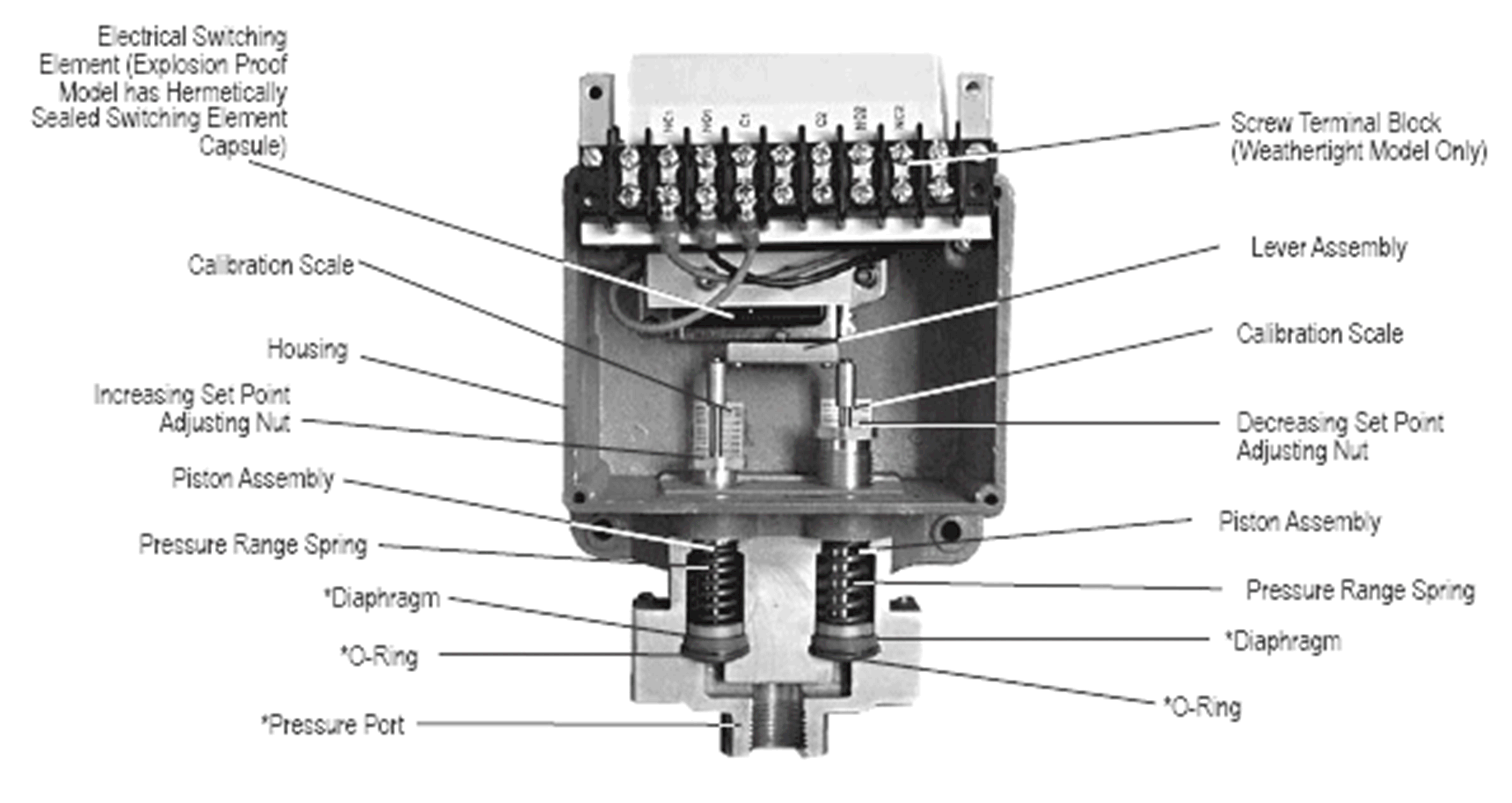
Refrigeration pressure switches act as electromechanical sensors that open or close electrical contacts based on the physical pressure of the refrigerant gas or liquid. Low-pressure switches interrupt the control circuit if the suction pressure drops below a safe threshold, which prevents the compressor from running dry or pulling a vacuum that draws moisture into the lines. High-pressure switches break the circuit if discharge pressure exceeds safe operating limits, shielding the compressor motor and sealed system components from over-pressurization.
The control circuit typically operates on lower voltage control power—such as 24V AC in commercial units or direct line voltage in smaller self-contained domestic appliances. Wires route from the power source through the thermostat, pass through the normally closed contacts of the safety pressure switches, and terminate at the compressor contactor coil or relay. If either switch trips, the control circuit loses continuity, immediately dropping out the contactor and stopping the compressor.
Regional electrical standards dictate wire color coding, insulation ratings, and enclosure requirements. For instance, installations governed by the National Electrical Code (NEC/NFPA 70) in the United States or the Canadian Electrical Code (CEC) in Canada follow specific guidelines for control circuit protection. Similar standards apply under BS 7671 in the United Kingdom and AS/NZS 3000 in Australia, where wire colors for live, neutral, and earth/ground conductors vary significantly by jurisdiction.
[Refrigeration System Safety] — According to guidelines from the Consumer Product Safety Commission (CPSC), electrical and pressure-related faults in sealed refrigeration equipment require verification by qualified technicians to prevent system ruptures and electrical shock.
Diagram Explanation and Key Components
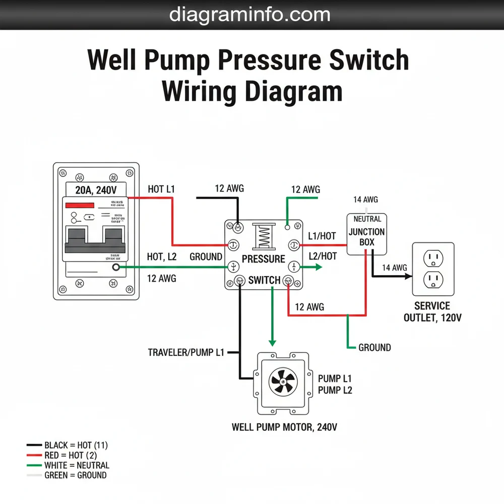
Reading a pressure switch wiring diagram refrigeration schematic requires familiarity with standard electrical symbols representing pressure bellows, microswitches, terminals, and relay coils. A basic schematic utilizes single-line or ladder diagrams where power rails run vertically down the sides, and control components bridge the space horizontally. Dashed lines often denote physical enclosures or factory-wired internal connections, while solid lines indicate field wiring installed by technicians.
Key components labeled on these diagrams include the common (COM), normally open (NO), and normally closed (NC) terminals of the pressure switch. Dual-pressure controls combine both low and high-pressure functions into a single housing, sharing a common electrical circuit path. Technicians must cross-reference terminal designations such as 1, 2, 4, or L and M against the manufacturer’s specific legend, because terminal numbering varies between brands like Danfoss, Johnson Controls, and Sporlan.
Mastering these visual indicators forms the foundation of Wiring Diagram Basics, enabling technicians to trace power flow accurately from the thermostat down to the physical compressor terminals.
Common Problems and Troubleshooting Methods
Systematic fault-finding is essential when a refrigeration compressor fails to start or short-cycles due to a tripped pressure control. Typical failures include stuck mechanical contacts inside the switch, pinched control wires, loose spade connectors resulting from compressor vibration, and out-of-calibration bellows that trip prematurely. A common technician mistake involves bypassing safety pressure switches during troubleshooting without first verifying actual system pressures with manifold gauges, which risks severe equipment damage.
Diagnostic execution begins by de-energizing the equipment and verifying a zero-energy state with a calibrated multimeter. Technicians then check for continuity across the pressure switch terminals while the system is offline. If an open circuit is detected when system pressures are within normal operating ranges, the switch has either failed internally or locked out due to a manual reset requirement. Further diagnosis involves monitoring voltage drops across the switch terminals while the control circuit is energized, ensuring power enters and exits the component without excessive resistance.
For complex control loops involving multiple safety interlocks, reviewing structured guidelines found in Wiring Troubleshooting helps isolate whether the fault originates from the pressure switch or an auxiliary component like an oil failure control.
Practical Tips and Safety Considerations
Mains-voltage and control circuit work on refrigeration systems demands strict adherence to electrical safety protocols. Prior to opening any electrical box or touching control terminals, de-energize the equipment and verify zero energy with a trusted meter. Where local regulations require it, ensure that installation and major electrical modifications are performed by a licensed electrician or qualified refrigeration technician.
Proper wire sizing and termination techniques prevent intermittent faults caused by heavy compressor vibration. Secure all spade connectors firmly, use weather-resistant or moisture-proof heat shrink where outdoor exposure occurs, and route control wiring away from hot discharge lines to prevent insulation degradation. Always consult the specific equipment manufacturer’s wiring manual for exact torque specifications and amperage ratings before finalizing any replacement.
Conclusion
Analyzing a pressure switch wiring diagram refrigeration schematic is a critical competency for maintaining safe, efficient cooling operations across residential and commercial sectors. By mastering core concepts, recognizing standardized diagram symbols, and executing methodical diagnostic procedures, technicians protect sensitive compressor hardware while ensuring compliance with regional electrical codes. Continued study of related control schematics can be advanced by exploring resources dedicated to Relay and Component Wiring Diagrams.
Quick Wiring Specifications & Terminal Guide
| Component / Circuit | Standard Wire Gauge | Recommended Protection |
|---|---|---|
| Control & Trigger Signals | 18 – 20 AWG | 5A – 7.5A Inline Fuse |
| Standard Auxiliary Load | 14 – 16 AWG | 15A – 20A Circuit Breaker |
| Main Power Feed / Supply | 10 – 12 AWG | 30A – 40A Heavy-Duty Relay |
Images References