Introduction
A five way trailer wiring diagram serves as the master blueprint for connecting 12V DC vehicle electrical systems to specialized towed equipment. This specific harness layout bridges standard lighting circuits with an auxiliary surge brake lockout function or a dedicated backup light circuit. Proper comprehension of this configuration ensures operational compliance on public roads across North America, the UK, Europe, and Australasia. Whether designing a custom tow rig or studying Vehicle Wiring Diagrams, mastering this layout prevents premature fuse failures, erratic light behavior, and unsafe towing conditions.
💡 Technical Key Takeaways:
- Core Focus: Diagnostic schematic and terminal connection layout for Five Way Trailer Wiring Diagram.
- Target Scope: Field technicians, automotive DIYers, and residential/commercial electricians.
- Safety Rule: Always disconnect the primary power source/battery terminal and verify zero voltage with a multimeter before touching wires.
Core Concepts and Wiring Fundamentals
The five-way connector layout builds upon the traditional flat four-pin configuration by adding a fifth conductor dedicated to a specific auxiliary load. Direct current power flows from the vehicle battery, through protective fuses or circuit breakers, across the tow vehicle chassis, and through the multi-pin connector to the trailer lamps and actuators.
Vehicle electrical standards such as those maintained by the Society of Automotive Engineers (SAE) in North America or equivalent international bodies outline minimum conductor sizing and insulation ratings. Circuit protection is mandatory to isolate short circuits before harness melting occurs. Ground continuity remains the single most critical factor in reliable operation, as painted surfaces, rust, and aluminum frames frequently create high-resistance return paths.
Fault Data — According to the National Highway Traffic Safety Administration (NHTSA), lighting and hitch failure categories account for a significant percentage of preventable trailer-related roadside incidents annually.
Diagram Explanation and Key Components
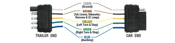
Reading a five way trailer wiring diagram requires translating standardized line types, wire color codes, and pinout schematics into physical connections. In standard North American flat-five configurations, the white wire serves as the chassis ground, the brown wire controls tail and running lights, the yellow wire operates the left turn signal and stop lamp, the green wire manages the right turn signal and stop lamp, and the fifth wire—typically blue—powers either electric backup lights or a hydraulic surge brake release solenoid.
International configurations may alter wire colors based on regional standards like ISO 1724 or local wiring codes, making visual verification of pin positions mandatory before making permanent splices. Schematic symbols depict fuses, relay coils, and switch contacts, aligning with principles often explored in Relay and Component Wiring Diagrams for auxiliary switching setups.
Common Problems and Troubleshooting Methods
Systematic fault-finding begins with verifying vehicle-side output before moving to the trailer harness itself. Typical field failures include intermittent ground paths causing ghost lighting, corrosion inside the molded plastic plug, and pinched wires running along the trailer frame rails.
Diagnosis requires a digital multimeter set to DC voltage or a dedicated 12V test light. The technician should first confirm a solid chassis ground at the tow vehicle socket. Next, activate individual tow vehicle functions—such as headlights, turn signals, and reverse gear—while probing the corresponding pins. If vehicle output checks out, trace the harness toward the trailer tongue, inspecting junctions, splices, and terminal blocks using techniques outlined in standard Wiring Troubleshooting procedures.
Practical Tips and Safety Considerations
Safe installation demands disconnecting the negative vehicle battery terminal before modifying or tapping into factory lighting circuits to prevent accidental shorts. Technicians must select correct wire gauge sizes matching the total ampacity load of all connected lamps and solenoids, utilizing heat-shrink butt connectors or soldered joints sealed with marine-grade adhesive tubing to block moisture ingress.
A frequent installation mistake involves relying on the hitch ball alone for grounding; always run a dedicated white ground wire from the trailer plug directly back to the tow vehicle chassis frame. Adhere strictly to local vehicle regulations regarding lighting visibility, breakaway systems, and auxiliary electrical loads.
Conclusion
Mastering the five way trailer wiring diagram empowers technicians and DIY builders to construct reliable, weather-resistant towing interfaces that perform consistently under harsh environmental conditions. Diligent attention to circuit protection, secure grounding, and accurate color-code identification eliminates guesswork during maintenance. For broader electrical system foundations and additional layout references, consult Wiring Diagram Basics to refine diagnostic skills further.
Quick Wiring Specifications & Terminal Guide
| Component / Circuit | Standard Wire Gauge | Recommended Protection |
|---|---|---|
| Control & Trigger Signals | 18 – 20 AWG | 5A – 7.5A Inline Fuse |
| Standard Auxiliary Load | 14 – 16 AWG | 15A – 20A Circuit Breaker |
| Main Power Feed / Supply | 10 – 12 AWG | 30A – 40A Heavy-Duty Relay |
Images References