Introduction
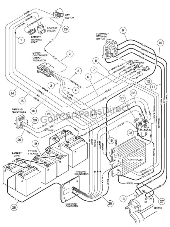
A club car headlight wiring diagram 48v provides the exact schematic blueprint needed to integrate lighting accessories into an electric golf cart’s high-voltage electrical architecture. Understanding this specific schematic matters because modern utility and golf vehicles operate on elevated direct current potentials that require careful voltage management to prevent catastrophic component damage. These layouts are utilized across maintenance fleets, residential neighborhood vehicles, and modified recreational carts throughout North America, the United Kingdom, Canada, and Australia. Proper comprehension of these diagrams improves installation quality, protects sensitive electronics, and ensures high troubleshooting accuracy during electrical modifications.
💡 Technical Key Takeaways:
- Core Focus: Diagnostic schematic and terminal connection layout for Club Car Headlight Wiring Diagram 48V.
- Target Scope: Field technicians, automotive DIYers, and residential/commercial electricians.
- Safety Rule: Always disconnect the primary power source/battery terminal and verify zero voltage with a multimeter before touching wires.
Core Concepts and Wiring Fundamentals
Golf carts operate on direct current (DC) circuits distributed from a main battery bank, necessitating precise control over voltage levels and current draw. A club car headlight wiring diagram 48v typically interfaces with the vehicle through one of two methods: tapping into a specific subset of 12-volt equivalent batteries within the pack or utilizing a step-down voltage reducer. Connecting 12-volt accessories directly across a portion of a 48-volt series string is a common field error that leads to severe battery imbalance, rapid sulfation, and premature pack failure.
Modern installations rely heavily on a DC-to-DC converter to safely step down the full pack voltage to a standardized 12-volt or 13.8-volt output. This regulated output feeds a dedicated fuse block, supplying protected power to switches, relays, and the headlight assemblies themselves. Fuses act as sacrificial protective devices, interrupting current flow during a short circuit and preventing wiring harnesses from overheating or catching fire. Relays serve as remote-controlled switches, allowing a low-current dashboard toggle switch to handle the higher current demands of halogen or high-output LED headlights without melting the dash switch contacts.
[Electrical Safety Foundation International (ESFI)] — Improperly installed aftermarket electrical accessories in low-speed vehicles are a leading cause of preventable DC circuit overloads and thermal events.
Diagram Explanation and Key Components
Reading a club car headlight wiring diagram 48v requires familiarity with standardized automotive and low-voltage schematic symbols, color-coding conventions, and physical connection points. Schematics utilize solid lines to represent active power feeds, dashed lines for control circuits, and distinct earth or chassis symbols for return paths. Standard wire color codes vary by region and manufacturer, where red typically denotes positive 48V or 12V supply lines, black or dark green indicates negative return paths, and striped variations designate switched accessory leads.
The primary components identified on the schematic include the 48-volt battery pack, the heavy-duty main tow/run switch, the voltage converter, the fuse panel, the dashboard rocker switch, and the headlight assemblies. The tow/run switch is a critical safety isolation point that must be placed in the tow position before any wiring modifications begin. Every component symbol correlates to physical pins or terminal blocks, which must be cross-referenced with Vehicle Wiring Diagrams to ensure correct polarity and pin insertion depth during assembly.
Common Problems and Troubleshooting Methods
Systematic fault-finding begins by verifying the operational status of the main battery pack and confirming that the voltage reducer is outputting the correct secondary voltage under load. Typical wiring faults involve open circuits caused by loose spade connectors, corroded ground terminals exposed to road debris, or blown fuses resulting from pinching insulation against the aluminum frame. Technicians approach these issues using a digital multimeter set to DC voltage or continuity mode, tracing the circuit sequentially from the power source downstream to the headlight plugs.
When headlights fail to illuminate, diagnostic procedures dictate checking the input and output sides of the dashboard switch, confirming relay coil actuation, and inspecting the condition of inline fuse holders. A common field observation involves intermittent flickering caused by high resistance at a crimp connection where moisture has entered the copper strands. Technicians must document all voltage drops across suspect switches and terminals, referencing standardized Wiring Troubleshooting methodologies to isolate faulty components rather than replacing parts randomly.
Practical Tips and Safety Considerations
Best practices for 48-volt accessory installations demand correct wire sizing, proper terminal crimping, and robust mechanical strain relief to withstand continuous vehicle vibration. Automotive-grade cross-linked polyethylene (XLPE) insulated wire should be selected based on total circuit ampacity, adhering to guidelines set forth by organizations such as the Society of Automotive Engineers (SAE) or applicable regional standards like the National Electrical Code (NEC) for vehicle safety practices in North America, or BS 7671 in the United Kingdom. Technicians must always disconnect the main battery pack or switch the vehicle into tow mode before servicing any electrical components to prevent severe arc flashes.
Common installation errors include utilizing inadequate wire gauges for long wire runs, omitting split-loom protective tubing near sharp metal edges, and neglecting to weatherproof exterior plug connections. Soldering connections is generally discouraged in high-vibration mobile applications unless proper mechanical strain relief is also utilized, as solder can crystallize and fracture over time. For foundational knowledge on reading complex schematics, refer to Wiring Diagram Basics to ensure accurate interpretation of complex multi-voltage systems.
Conclusion
Mastering a club car headlight wiring diagram 48v bridges the gap between safe electrical theory and reliable mechanical execution on low-speed electric vehicles. Adhering to manufacturer specifications, utilizing proper voltage conversion equipment, and executing systematic diagnostic checks ensures long-term system integrity and prevents costly electrical failures. Safe practices protect both the technician and the vehicle’s delicate electronic control modules during every phase of installation or repair. For further exploration of auxiliary systems, consult Relay and Component Wiring Diagrams to expand diagnostic proficiency across diverse electrical platforms.
Quick Wiring Specifications & Terminal Guide
| Component / Circuit | Standard Wire Gauge | Recommended Protection |
|---|---|---|
| Control & Trigger Signals | 18 – 20 AWG | 5A – 7.5A Inline Fuse |
| Standard Auxiliary Load | 14 – 16 AWG | 15A – 20A Circuit Breaker |
| Main Power Feed / Supply | 10 – 12 AWG | 30A – 40A Heavy-Duty Relay |
Images References