Introduction
Golf cart brake switch wiring manages the electrical circuit that activates the rear tail lights, brake lights, or regenerative braking signals whenever the brake pedal is depressed. Understanding this circuitry matters for both street-legal compliance and operational safety on private property, preventing rear-end collisions in low-speed environments. This mechanism appears across electric and gas utility vehicles, personal transport carts, and neighborhood electric vehicles found globally in regions governed by bodies such as the Society of Automotive Engineers (SAE) or international equivalents. Mastering this circuit layout improves troubleshooting accuracy, ensures reliable accessory integration, and extends the lifespan of low-voltage vehicle networks.
💡 Technical Key Takeaways:
- Core Focus: Diagnostic schematic and terminal connection layout for Golf Cart Brake Switch Wiring.
- Target Scope: Field technicians, automotive DIYers, and residential/commercial electricians.
- Safety Rule: Always disconnect the primary power source/battery terminal and verify zero voltage with a multimeter before touching wires.
Core Concepts and Wiring Fundamentals
Low-voltage direct current power supplies drive the typical golf cart electrical architecture, operating predominantly on 12-volt systems stepped down from high-voltage battery packs, or running on standalone 12-volt auxiliary batteries in gas-powered variants. A functional brake circuit relies on a normally open mechanical or hydraulic switch mounted near the pedal linkage, complete wiring harnesses, inline fuses for short-circuit protection, and secure chassis or negative return paths. When an operator presses the brake pedal, the switch closes, completing the circuit from the power source through the switch contacts to the rear lighting load.
Vehicle power distribution networks depend heavily on correct component pairing, which can be explored further in resources dedicated to Relay and Component Wiring Diagrams. In many modern cart designs, the low current passing through the pedal switch is routed into a solid-state controller or an electromechanical relay rather than directly powering high-draw incandescent bulbs. This prevents switch contact pitting and thermal degradation over thousands of actuation cycles. Ensuring that every crimp connector, terminal eyelet, and fuse holder matches the specified current carrying capacity prevents excessive voltage drop and intermittent lighting failures.
[Vehicle Electrical Safety] — According to the Society of Automotive Engineers (SAE), low-voltage DC automotive and utility vehicle circuits require proper overcurrent protection sized strictly to wire ampacity to prevent thermal overload and insulation breakdown.
Diagram Explanation and Key Components
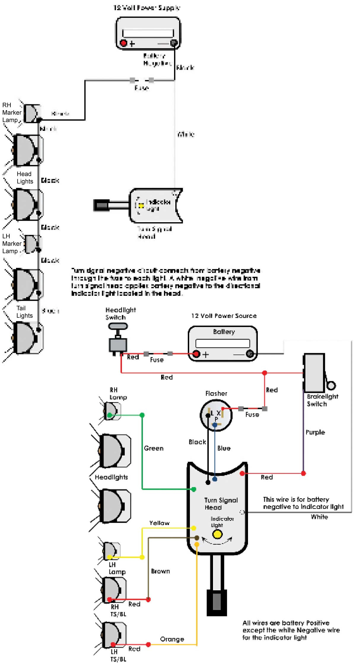
Reading a schematic for golf cart brake switch wiring requires recognizing standardized schematic symbols, including the open-contact switch icon, fused power supply lines, and grounding symbols. Schematics use specific line weights and color-coding conventions to trace circuits from the main power bus, through the dash-mounted or pedal-mounted switch, out to the rear light assemblies, and back to the negative ground bus. In North American builds, primary 12-volt accessory feeds often utilize red or yellow conductors, while ground returns utilize black. Conversely, international builds adhering to alternative standards may implement distinct color identifiers for power and return paths.
A complete understanding of these visual languages is essential, and technicians frequently cross-reference manufacturer schematics with resources found in Vehicle Wiring Diagrams. The primary components on the diagram typically consist of a fused 12V positive feed, the mechanical microswitch or magnetic proximity sensor, output leads to the brake lamp filaments or LED clusters, and the system ground. Field observation reveals that physical wiring often deviates from factory schematics due to aftermarket lighting kits added by previous owners, making visual verification of physical wire paths mandatory during diagnostic procedures.
Common Problems and Troubleshooting Methods
Systematic fault-finding begins with identifying whether the brake lights remain permanently illuminated, fail to activate entirely, or flicker during pedal travel. Technicians diagnose these symptoms by performing a structured series of voltage drop tests, continuity checks, and visual inspections using a digital multimeter set to DC volts and ohms. The diagnostic process typically starts at the fuse panel to verify power supply integrity, moves to the switch terminals to check for incoming and outgoing voltage when the pedal is depressed, and concludes at the light socket grounds.
Typical failure points include corroded spade terminals exposed to moisture beneath the floorboard, misadjusted microswitch actuators that fail to close the contacts fully, and broken wire strands caused by constant mechanical flexing near the pedal pivot point. Technicians must also inspect the ground return path, as high resistance in the chassis ground will cause erratic light behavior or total circuit failure. Proper diagnostic technique treats these symptoms methodically rather than relying on guesswork, ensuring accurate identification of faulty components before any replacement takes place.
Practical Tips and Safety Considerations
Safe installation and maintenance practices dictate that technicians always disconnect the main battery pack or auxiliary 12-volt battery before servicing any portion of the vehicle electrical harness to prevent accidental short circuits and arcing. Technicians should utilize marine-grade heat-shrink butt connectors, dielectric grease on exposed terminals, and properly rated copper conductors to withstand harsh environmental conditions such as moisture, road salt, and vibration. Wire sizing must adhere to standard automotive guidelines to maintain minimal resistance across extended runs.
For complex auxiliary setups or custom accessory integrations, referencing standardized practices available in Wiring Diagram Basics ensures compliance with sound electrical principles. A common mistake during repairs is bypassing inline fuses or substituting higher-amperage fuses when a circuit keeps blowing, which masks underlying shorts and creates severe fire hazards. Always verify correct switch mechanical alignment and test circuit operation through multiple actuation cycles before returning the vehicle to service.
Conclusion
Mastering golf cart brake switch wiring enhances both vehicle reliability and personal safety through methodical diagnosis and clean installation practices. Proper attention to circuit fundamentals, accurate schematic interpretation, and diligent safety procedures prevent recurring electrical faults in low-voltage transport vehicles. By understanding how power moves from the source through the switch mechanism to the output devices, technicians and DIY enthusiasts alike can maintain efficient, safe electrical systems. Further exploration of related automotive circuits can be continued through comprehensive guides on Wiring Troubleshooting to build greater proficiency in electrical diagnostics.
Quick Wiring Specifications & Terminal Guide
| Component / Circuit | Standard Wire Gauge | Recommended Protection |
|---|---|---|
| Control & Trigger Signals | 18 – 20 AWG | 5A – 7.5A Inline Fuse |
| Standard Auxiliary Load | 14 – 16 AWG | 15A – 20A Circuit Breaker |
| Main Power Feed / Supply | 10 – 12 AWG | 30A – 40A Heavy-Duty Relay |
Images References