Introduction
A car headlights on warning wiring diagram illustrates the electrical circuit responsible for triggering an audible chime or visual indicator when the driver’s door opens while the headlights remain illuminated. This safety feature prevents accidental battery drainage, a frequent issue in modern and classic vehicles alike. Understanding this circuit improves diagnostic accuracy, prevents unnecessary component replacement, and ensures correct electrical integration during custom repairs. These diagrams map out the interaction between ignition switches, door jamb triggers, headlamp control switches, and integrated body control modules.
💡 Technical Key Takeaways:
- Core Focus: Diagnostic schematic and terminal connection layout for Car Headlights On Warning Wiring Diagram.
- Target Scope: Field technicians, automotive DIYers, and residential/commercial electricians.
- Safety Rule: Always disconnect the primary power source/battery terminal and verify zero voltage with a multimeter before touching wires.
Core Concepts and Wiring Fundamentals
The headlights-on warning circuit relies on a dual-input logic configuration, requiring two separate conditions to be met before activating the warning buzzer. Power typically originates from the battery through a fused constant 12-volt source, feeding the headlamp switch or instrument cluster warning module. Ground paths are usually controlled by the driver-side door jamb switch, which completes the circuit only when the door opens.
In older automotive architectures, this circuit functioned via a simple electromechanical buzzer connected in series between the headlight circuit and the door switch. Modern multiplexed systems route these inputs through a Body Control Module (BCM), which processes the switch states digitally and commands the instrument cluster to sound an integrated chime. Familiarity with Vehicle Wiring Diagrams is essential for tracing these power and signal paths accurately across different vehicle generations.
Vehicle electrical safety standards, such as those established by SAE International, require strict isolation and fusing on accessory circuits to prevent thermal events caused by persistent current draws or short circuits. — SAE International
Diagram Explanation and Key Components
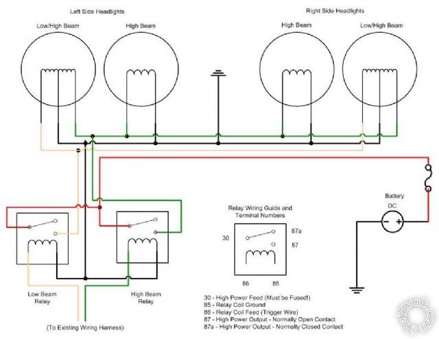
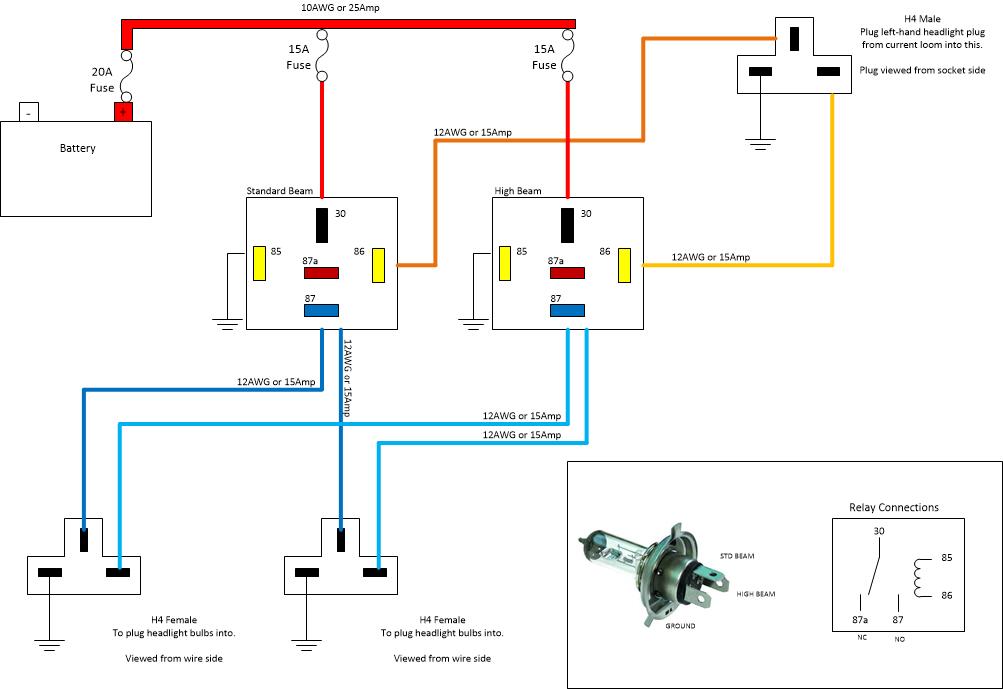
Reading a car headlights on warning wiring diagram involves recognizing specific symbols for switches, diodes, resistors, and control modules. The headlight switch is typically depicted with contacts that close when the knob is pulled to the parking lamp or headlamp position. The door jamb switch appears as a normally open single-pole, single-throw (SPST) switch that closes to ground when the plunger extends upon door opening.
Wire color codes vary significantly by region and manufacturer, adhering to standards set by organizations like the Society of Automotive Engineers in North America or DIN standards in Europe. Technicians must cross-reference factory service manuals for precise wire insulation colors and terminal cavity designations. Understanding Wiring Diagram Basics helps decode line types, representing power feeds, ground returns, and data bus lines clearly.
Common Problems and Troubleshooting Methods
Troubleshooting the warning chime requires a systematic diagnostic approach rather than random part replacement. Typical failures include a stuck-closed or corroded door jamb switch, a faulty headlamp switch contact that fails to route the ignition-off signal, or a blown fuse supplying the warning module. A persistent failure to sound the chime usually points to an open circuit in the ground path provided by the door switch.
Diagnosis begins by verifying battery voltage at the fuse block, followed by checking continuity through the door jamb switch using a digital multimeter. Technicians should isolate the circuit and test for voltage drops across suspect connectors before condemning any control module. For deeper electrical analysis techniques, reviewing Wiring Troubleshooting guides provides additional methodologies for isolating complex intermittent faults.
Practical Tips and Safety Considerations
Automotive electrical work demands strict adherence to safety protocols, particularly regarding short circuits that can damage sensitive microprocessors. Always disconnect the negative battery terminal before probing wiring harnesses or replacing integrated modules, unless live testing is explicitly required by diagnostic procedures. Use insulated hand tools and quality digital multimeters rated for automotive environments.
When repairing damaged harness sections, utilize proper crimp connectors lined with adhesive heat-shrink tubing to prevent moisture ingress and subsequent corrosion. A common mistake during custom radio or alarm installations is splicing into the headlight warning circuit incorrectly, which can bypass safety logic or cause parasitic drains. Proper wire sizing and adherence to manufacturer specifications ensure long-term reliability and fire prevention.
Conclusion
Mastering the car headlights on warning wiring diagram empowers technicians and DIY enthusiasts to resolve persistent battery-drain issues efficiently and safely. By understanding power distribution, switch logic, and signal routing, electrical faults can be isolated with precision. Always prioritize safe disconnection practices and consult accurate factory references before initiating any repair. Explore Relay and Component Wiring Diagrams to further expand diagnostic capabilities across all vehicle electrical systems.
Quick Wiring Specifications & Terminal Guide
| Component / Circuit | Standard Wire Gauge | Recommended Protection |
|---|---|---|
| Control & Trigger Signals | 18 – 20 AWG | 5A – 7.5A Inline Fuse |
| Standard Auxiliary Load | 14 – 16 AWG | 15A – 20A Circuit Breaker |
| Main Power Feed / Supply | 10 – 12 AWG | 30A – 40A Heavy-Duty Relay |
Images References