Introduction
Motorola alternator wiring refers to the specific electrical configuration and terminal layout found on vintage and heavy-duty charging systems originally manufactured by Motorola, which later became standard in various automotive, marine, and industrial applications. Mastering this specific configuration matters because these external voltage regulator systems operate fundamentally differently from modern internal-regulator alternators, frequently confusing technicians accustomed to plug-and-play architecture. This electrical arrangement involves routing high-current output lines and precise excitation circuits through distinct physical terminals marked as BAT, EXC, and STA. Understanding these circuits improves installation quality, prevents catastrophic wiring harnesses fires, and ensures accurate troubleshooting when a classic vehicle or industrial engine fails to charge the battery properly.
💡 Technical Key Takeaways:
- Core Focus: Diagnostic schematic and terminal connection layout for Motorola Alternator Wiring.
- Target Scope: Field technicians, automotive DIYers, and residential/commercial electricians.
- Safety Rule: Always disconnect the primary power source/battery terminal and verify zero voltage with a multimeter before touching wires.
Core Concepts and Wiring Fundamentals
The Motorola charging architecture relies on a three-wire or four-wire setup that separates the power production from the voltage regulation duties, often pairing the alternator with a mechanical or solid-state external regulator. High-current generation flows from the main output terminal, conventionally labeled BAT, directly to the vehicle’s electrical distribution bus or battery positive post through a heavy-gauge copper conductor protected by fusible links.
The excitation circuit, marked as EXC or IGN, supplies initial battery voltage to the rotor field windings through the ignition switch to create the necessary magnetic field for power generation. Without this initial excitation current flowing through the regulator, the alternator remains dormant and produces zero output regardless of engine rotational speed.
An auxiliary terminal, labeled STA for stator, provides an alternating current signal proportional to engine speed, which frequently drives electric choke relays, tachometers, or the charge indicator warning lamp circuit. Maintaining clean, low-resistance connections across every terminal is mandatory for proper operation, as high resistance creates excessive heat and voltage drop.
Ground integrity is another critical design element in these systems, because many older alternator housings rely strictly on clean metal-to-metal contact with the engine block mounting brackets to complete the internal circuit. Adding a dedicated auxiliary ground wire directly from the alternator body to the engine block or battery negative terminal eliminates intermittent charging faults caused by vibration, corrosion, or paint buildup on mounting surfaces.
[Electrical system failures in mobile machinery frequently stem from high-resistance connections and compromised grounds rather than total component failure] — [Society of Automotive Engineers (SAE) Technical Standards]
Diagram Explanation and Key Components
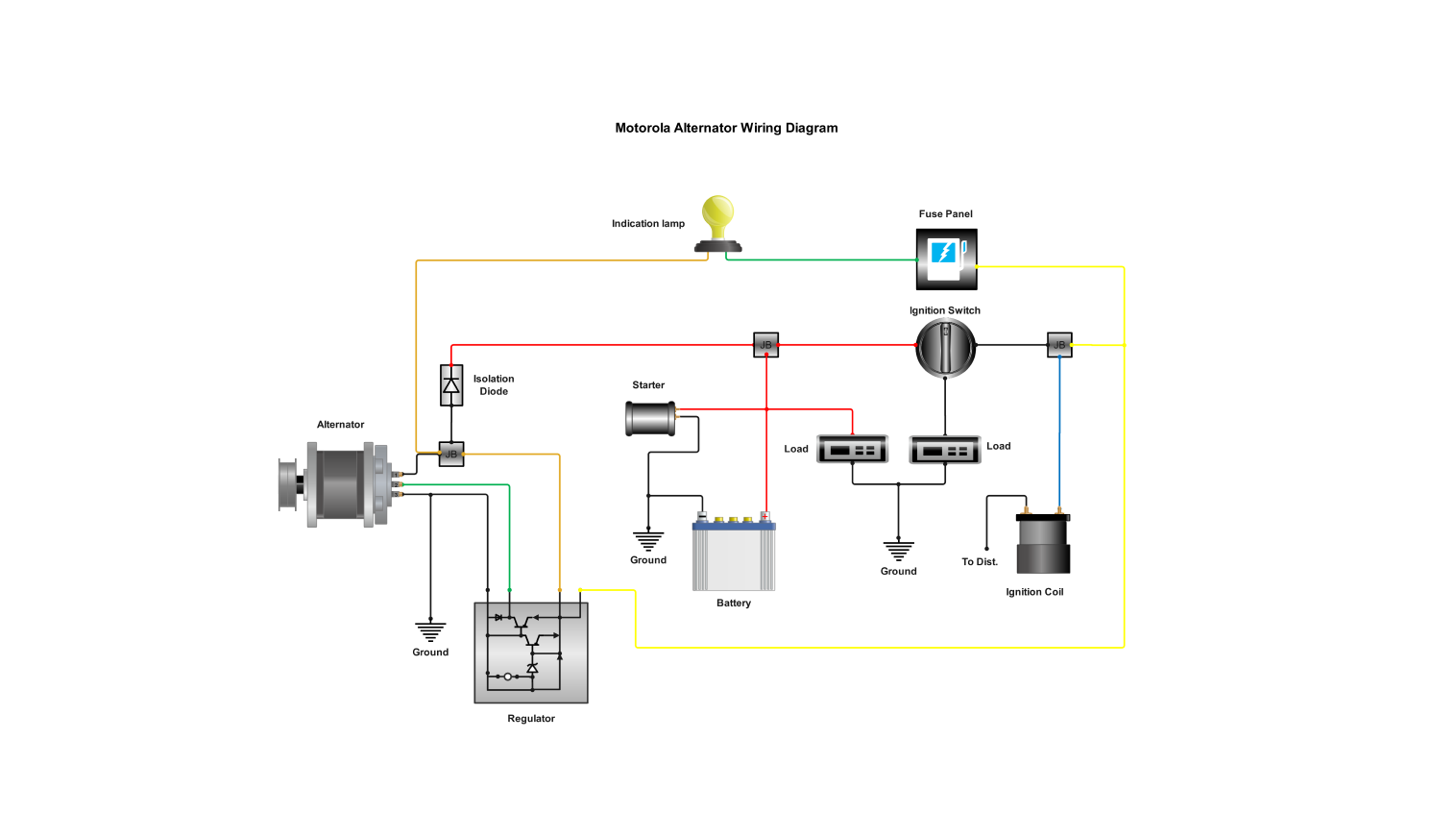
Reading technical schematics for motorola alternator wiring requires interpreting standardized alphanumeric terminal markings and tracing circuits through external regulator blocks. The primary symbols on these schematics include the rotating field coil, the three-phase stator windings, the diode trio rectifying bridge, and the external voltage regulator containing vibrating contact points or transistorized switching gates. Color codes vary significantly depending on the original equipment manufacturer, but standard aftermarket replacement harnesses generally utilize thick red wires for battery output, blue or brown wires for field excitation, and white or black wires for stator connections.
When examining these Vehicle Wiring Diagrams, technicians must trace the path from the battery positive terminal through the dash-mounted ignition switch to ensure the regulator receives a switched 12-volt reference signal. The regulator itself acts as an electronic gatekeeper, modulating the ground side or supply side of the field current to maintain a steady system voltage between 13.5 and 14.5 volts under varying electrical loads.
Understanding Wiring Diagram Basics helps demystify how dash warning lamps interact with the auxiliary terminals, where the bulb acts as both an indicator and a source of initial resistance for the excitation circuit. If this specific indicator bulb burns out in certain vintage circuits, the alternator fails to excite upon startup, illustrating why every single trace on the schematic serves a dual electrical and mechanical purpose.
Common Problems and Troubleshooting Methods
Typical faults in these charging setups involve open circuits in the field wire, shorted diodes within the internal rectifier bridge, corroded regulator terminals, and catastrophic ground failures. A systematic diagnostic approach begins with a visual inspection of all ring terminals, crimp connectors, and fusible links for signs of thermal damage, melting, or green copper corrosion.
Testing proceeds with a digital multimeter set to DC volts to measure battery voltage with the engine off, which should read approximately 12.6 volts on a fully charged 12V lead-acid battery. Next, start the engine and measure across the battery terminals; a healthy system registers an elevated reading between 13.5 and 14.5 volts, confirming proper charging output.
When voltage remains static or drops below battery resting level, technicians perform voltage drop testing across the main BAT cable and check for presence of battery voltage at the EXC terminal with the ignition key turned to the run position. If voltage is missing at the excitation terminal, the fault lies within the dash wiring, ignition switch, or blown dash fuses, rather than the alternator itself. Utilizing resources focused on Wiring Troubleshooting assists in isolating whether the external regulator has welded points or if the stator has developed an internal open winding.
Practical Tips and Safety Considerations
Working on automotive and industrial charging systems demands rigorous adherence to safety protocols, starting with disconnecting the battery negative cable before servicing any high-current wiring connections to prevent accidental arcing and tool welding. Because these circuits carry substantial amperage directly from the battery without immediate overcurrent protection prior to the main fusible link, any inadvertent slip of a wrench against grounded chassis metal can cause severe burns or electrical fires.
Wire sizing must match or exceed original equipment manufacturer specifications, typically utilizing heavy 8-gauge or 10-gauge copper wiring for the main output circuit to handle maximum electrical loads without excessive thermal generation. When replacing ring terminals, mechanical crimping tools followed by adhesive-lined heat shrink tubing provide superior environmental sealing against moisture and engine oil intrusion compared to standard electrical tape.
Regional standards, such as SAE guidelines in North America or relevant British Standards in the UK, dictate specific wiring practices and insulation temperature ratings for engine bay environments operating under high ambient heat. Always verify local technical requirements and consult qualified professionals where heavy industrial modifications or complex electrical integration is involved.
Conclusion
Properly configuring and maintaining motorola alternator wiring ensures reliable electrical generation for classic vehicles, agricultural machinery, and marine applications relying on external regulation. By methodically verifying every terminal connection, ensuring pristine ground paths, and accurately interpreting system schematics, technicians and enthusiasts can resolve charging anomalies safely and effectively. Careful attention to wire gauge selection, terminal cleanliness, and structured diagnostic testing prevents recurring failures and extends the operational lifespan of vintage charging hardware. For further exploration of related electrical architectures, consult guides covering Relay and Component Wiring Diagrams.
Quick Wiring Specifications & Terminal Guide
| Component / Circuit | Standard Wire Gauge | Recommended Protection |
|---|---|---|
| Control & Trigger Signals | 18 – 20 AWG | 5A – 7.5A Inline Fuse |
| Standard Auxiliary Load | 14 – 16 AWG | 15A – 20A Circuit Breaker |
| Main Power Feed / Supply | 10 – 12 AWG | 30A – 40A Heavy-Duty Relay |
Images References