Introduction
An electrical circuit diagram of reverse lights maps the 12-volt or 24-volt direct current path that powers the rear hazard and backing illumination of a vehicle. This system relies on a dedicated power source, a control switch, protection devices, and load-bearing lamps to signal backing maneuvers to other drivers and pedestrians. Understanding this schematic prevents incorrect diagnostic assumptions and ensures compliance with automotive lighting standards established by organizations such as the Society of Automotive Engineers (SAE) or equivalent international bodies. Whether working on a passenger car, heavy commercial truck, or trailer setup, mastering these diagrams guarantees faster fault isolation and reliable repairs. Safe practices, such as disconnecting the vehicle battery before probing sensitive circuits, prevent accidental short circuits and module damage.
💡 Technical Key Takeaways:
- Core Focus: Diagnostic schematic and terminal connection layout for Electrical Circult Diagram Of Reverse Lights.
- Target Scope: Field technicians, automotive DIYers, and residential/commercial electricians.
- Safety Rule: Always disconnect the primary power source/battery terminal and verify zero voltage with a multimeter before touching wires.
Core Concepts and Wiring Fundamentals
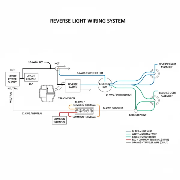
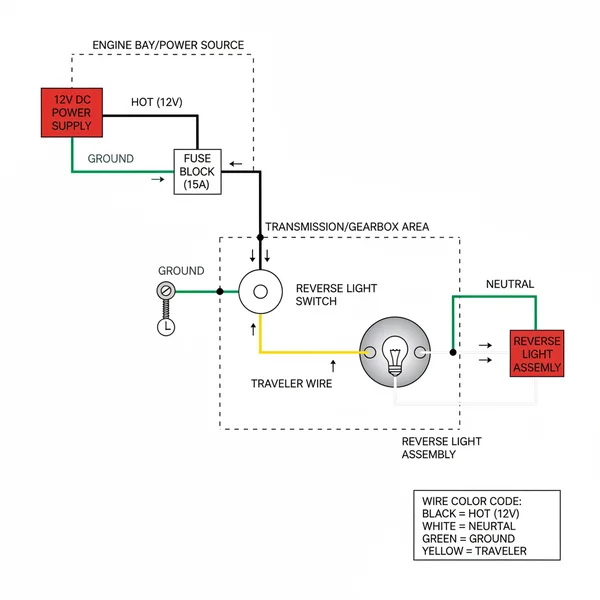
The reverse light circuit operates on a straightforward switched-power architecture found throughout Vehicle Wiring Diagrams. Power originates at the battery and travels through the ignition switch or the body control module to a designated fuse within the interior or under-hood power distribution center. Fuses protect the wiring harness from overcurrent conditions by interrupting the path if a short develops.
From the fuse, current flows to the transmission-mounted backup light switch in manual vehicles or the gear selector range sensor (neutral safety switch) in automatic transmissions. When the driver selects reverse gear, the physical contacts close, completing the circuit and sending voltage down the chassis harness to the rear lamp assemblies. Modern vehicles often route this signal through a body control module, which then energizes a solid-state switch or an electromechanical relay to feed the rear lamps.
The circuit terminates at the bulb sockets, where the electrical energy converts into light and thermal output. Finally, the current returns to the vehicle chassis through a dedicated ground wire or a metal-to-metal body ground point. A high-resistance ground path remains one of the most frequent culprits behind dim lighting or complete circuit failure.
[Finding] — According to the Society of Automotive Engineers (SAE) standards, backup lamps must emit white light and provide adequate rear visibility during backing maneuvers, requiring strict circuit integrity and minimal voltage drop across the wiring harness.
Diagram Explanation and Key Components
Reading an electrical circult diagram of reverse lights requires familiarity with standard schematic symbols, line types, and alphanumeric wire identification codes. Mastery of Wiring Diagram Basics allows technicians to quickly distinguish between continuous power lines, switched ignition feeds, and ground symbols. In these schematics, straight solid lines represent primary power conductors, while zigzag lines or specific blocks denote resistive loads or control modules.
Color coding on automotive schematics varies by region and manufacturer. In North America, manufacturers often use alphanumeric codes printed directly on the insulation to identify wire color and gauge, whereas European manufacturers rely on a standardized numeric color code system defined by DIN standards. Tracing a schematic involves locating the power source on the left or top of the page, following the line through the switch symbol, and ending at the load and ground symbols on the right or bottom.
Key components include the fuse, which protects against overloads; the reverse switch, which acts as the primary gatekeeper of voltage; and the bulb filaments or LED driver boards. Connector pinout callouts on the diagram show exact cavity locations, helping technicians verify terminal tension and continuity without piercing wire insulation.
Common Problems and Troubleshooting Methods
Systematic fault-finding using structured methods from Wiring Troubleshooting resolves intermittent or total reverse light failure efficiently. The diagnostic process begins with a simple visual check of the bulbs and the fuse panel. A blown fuse immediately points toward a short-to-ground in the downstream harness or a failing lamp socket.
When fuses remain intact but the lights fail to illuminate, a digital multimeter becomes the primary diagnostic tool. The technician checks for battery voltage at the input side of the reverse switch with the ignition on and the gear selector in reverse. If voltage enters the switch but does not exit when engaged, the switch itself is defective. If voltage passes through the switch but never reaches the rear bulb sockets, an open circuit exists somewhere along the main chassis harness or inline connector.
Corrosion inside trailer wiring connectors and rear lamp housings represents another frequent issue in regions subjected to road salt and winter moisture. Voltage drop testing across the ground circuit isolates hidden high-resistance faults that simple continuity checks might miss.
Practical Tips and Safety Considerations
Executing repairs on automotive lighting circuits demands adherence to proper electrical techniques, such as using heat-shrink waterproof butt connectors or solder-free crimping tools protected by marine-grade adhesive tubing. Taping wires with standard household electrical tape introduces moisture ingress, leading to future corrosion and lighting failure.
When replacing fuses, always match the exact amperage rating specified by the manufacturer. Installing an oversized fuse creates a severe fire hazard, as the wiring harness will melt before the fuse blows during a fault condition. Mechanics and DIY enthusiasts must also disconnect the negative battery terminal before cutting into main harnesses or replacing body control modules to prevent accidental voltage spikes.
Conclusion
Interpreting an electrical circult diagram of reverse lights empowers technicians and enthusiasts to diagnose faults logically rather than guessing blindly. By understanding the interaction between fuses, switches, wiring harnesses, and ground points, anyone can restore safe and legal operation to a vehicle lighting system. Careful adherence to schematic symbols, regional color codes, and safety protocols ensures long-lasting repairs. For further exploration of vehicle electrical layouts, consult resources on Relay and Component Wiring Diagrams to expand diagnostic expertise.
Quick Wiring Specifications & Terminal Guide
| Component / Circuit | Standard Wire Gauge | Recommended Protection |
|---|---|---|
| Control & Trigger Signals | 18 – 20 AWG | 5A – 7.5A Inline Fuse |
| Standard Auxiliary Load | 14 – 16 AWG | 15A – 20A Circuit Breaker |
| Main Power Feed / Supply | 10 – 12 AWG | 30A – 40A Heavy-Duty Relay |
Images References