Understanding the electrical blueprint for an air conditioning compressor is paramount for anyone working with HVAC systems. Mastering these detailed graphical representations significantly enhances practical electrical skills, leading to safer installations, more efficient troubleshooting, and a deeper comprehension of how complex machinery operates. Each line, symbol, and connection holds critical information, providing a precise roadmap for the electrical flow within an air conditioning unit. Proficiency in interpreting these documents is not merely a technical skill but a foundational aspect of ensuring operational integrity and preventing potential electrical hazards.
By diligently studying and comprehending the electrical layout for these crucial components, one can achieve a multitude of advantages. This knowledge enables accurate and rapid diagnosis of system malfunctions, pinpointing issues such as faulty relays, open circuits, or shorted windings with confidence. It also facilitates correct and safe replacement of components like capacitors, contactors, or the compressor itself, ensuring that all electrical connections are made according to manufacturer specifications. Furthermore, a solid grasp of these electrical schematics empowers individuals to plan and execute maintenance tasks more effectively, minimizing downtime and extending the lifespan of the air conditioning equipment.
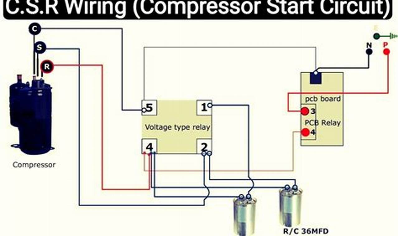
A typical electrical schematic for an air conditioning compressor features a structured layout, often beginning with the power supply and meticulously tracing the circuit through various protective devices and control components. Common symbols encountered include squares or circles representing motors (specifically the compressor motor), rectangles for contactors and relays, parallel lines for capacitors, and various shapes for fuses, circuit breakers, and thermal overload protectors. Lines denote the electrical conductors, with different line types sometimes indicating specific functions like control wires versus power wires. Understanding the standardized symbols and their interconnections is essential for correctly interpreting the flow of electricity and control signals within the system.
To effectively read and utilize these diagrams, begin by identifying the power source and following the main power lines to the compressor motor. Next, trace the control circuit, which typically involves the thermostat, low-pressure and high-pressure switches, and the contactor coil. Pay close attention to the sequence of operation as dictated by the control logic. Practical application involves using a multimeter to verify voltage at specific points, check for continuity across components, or confirm resistance values in windings. Always ensure power is disconnected before performing any work, and verify the absence of voltage with appropriate testing equipment. Developing the habit of systematically tracing circuits and understanding component functions will greatly enhance diagnostic capabilities.
Beyond the fundamental principles, several additional tips can aid in mastering electrical layouts for air conditioning systems. Always cross-reference the diagram with the actual physical components of the unit to build a stronger mental model. Consider starting with simpler diagrams before moving to more complex ones. Supplementary resources such as dedicated HVAC electrical textbooks, online forums where experienced technicians share insights, and manufacturer-specific service manuals can provide invaluable context and practical scenarios. Practicing tracing different circuit paths and identifying potential failure points on various schematics will solidify understanding and improve troubleshooting speed. Continuous learning and hands-on application are key to developing expertise.
In conclusion, mastering the electrical blueprint for an air conditioning compressor is an indispensable skill for anyone involved in the installation, maintenance, or repair of HVAC systems. This proficiency not only ensures safety and compliance but also significantly boosts troubleshooting efficiency and overall operational confidence. By diligently applying the principles of reading electrical schematics, individuals can unlock a deeper understanding of complex electrical systems. Explore more wiring resources or diagrams on readwires.com to further enhance electrical knowledge and practical application.
