Electrical systems, though often unseen, are the lifeblood of modern machinery. Within a riding lawn mower, a meticulously designed network of wires ensures every component functions harmoniously. Understanding this network is essential for effective maintenance and repair, enabling informed troubleshooting and preventing costly damage.
Mastering the ability to interpret these schematics unlocks a multitude of benefits. It empowers individuals to diagnose electrical issues with greater accuracy, minimizing downtime and reducing the need for professional assistance. Furthermore, a solid understanding promotes safer practices during repairs and modifications, protecting both the equipment and the operator.
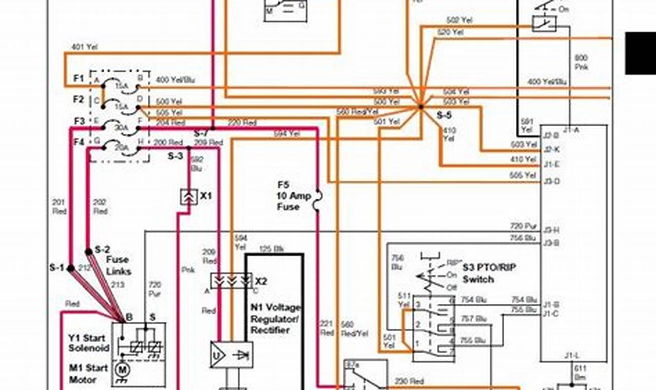
These diagrams typically present a simplified representation of the electrical system. Wires are shown as lines connecting various components represented by standardized symbols. Common symbols include those for batteries, switches, solenoids, fuses, and motors. The diagram illustrates the flow of electricity, often indicating wire colors and gauge sizes for accurate identification.
To effectively interpret and utilize the schematic, begin by identifying the primary power source usually the battery. Trace the circuit paths, noting the sequence of components and switches. When troubleshooting, compare the actual electrical flow with the diagram to pinpoint discrepancies. A multimeter is an invaluable tool for verifying voltage and continuity at various points in the circuit. Remember to disconnect the battery before commencing any electrical work.
For enhanced understanding, consider exploring resources such as manufacturer’s service manuals and online forums dedicated to lawn mower repair. These platforms often contain detailed explanations, troubleshooting guides, and user experiences that can supplement the information presented in the schematic. Practice reading various electrical diagrams to build familiarity with common symbols and circuit configurations. Online tools may also offer interactive simulations for hands-on learning.
Proficiency in interpreting electrical schematics is a valuable asset for anyone involved in the maintenance or repair of machinery. It empowers individuals to tackle electrical challenges with confidence and competence, leading to more efficient troubleshooting and safer working practices. Continue exploring other related diagrams and resources to further enhance your expertise.
