Electrical wiring forms the backbone of countless systems, from simple household appliances to complex industrial machinery. A clear understanding of wiring principles, and particularly the ability to interpret schematic representations, is essential for anyone working with electrical circuits. Mastering these diagrams significantly enhances practical electrical skills, promotes safer working practices, and minimizes the risk of electrical hazards.
Skillfully interpreting and utilizing schematic representations leads to numerous benefits. Improved troubleshooting capabilities are realized, allowing for quicker identification and resolution of electrical faults. Electrical installations become safer and more reliable due to a deeper understanding of circuit pathways. Furthermore, the planning phase of any wiring project benefits from this comprehension, ensuring accurate material procurement and efficient execution. This knowledge fosters confidence in tackling electrical tasks, empowering individuals to manage their electrical systems effectively.
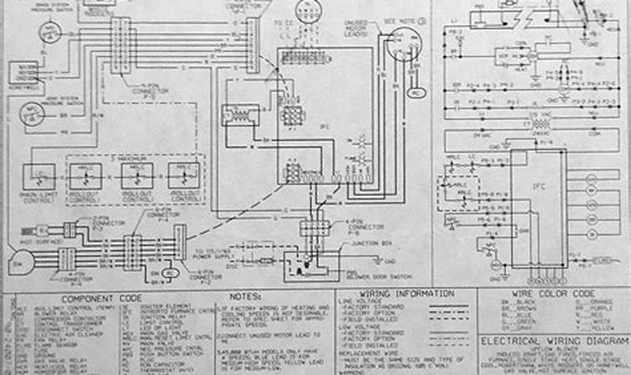
Diagrams of this nature generally present a simplified view of the circuit, focusing on the connections between components rather than their physical arrangement. Standardized symbols represent various electrical components such as resistors, capacitors, switches, and relays. Lines indicate wires, and their intersections depict connections. The diagram often includes labels identifying components and wire gauges. Power sources are also represented, showing voltage and polarity. Careful attention to these symbols and their arrangement is crucial for accurate interpretation.
To effectively read and utilize the schematic, begin by identifying the power source and tracing its path through the circuit. Pay close attention to the connections between components, noting the polarity of polarized elements like diodes and capacitors. Use a multimeter to verify voltage and continuity at key points in the circuit. When troubleshooting, compare the actual circuit behavior to the expected behavior as depicted in the diagram. This comparison allows for the identification of discrepancies, leading to the discovery of faults such as open circuits, short circuits, or component failures. For electricians, hobbyists, and homeowners, this systematic approach provides a reliable method for understanding and resolving electrical issues.
Supplementing diagram reading skills with practical experience is highly beneficial. Always prioritize safety by disconnecting power before working on any electrical circuit. Consider using wire strippers and crimpers for professional-looking connections. For further learning, resources such as the National Electrical Code (NEC) and manufacturer’s specifications provide valuable information. Online forums and communities dedicated to electrical work can also offer support and insights. Explore other schematics for different circuit types to broaden understanding and expertise.
Proficiency in interpreting schematic representations is a valuable skill applicable to a wide range of electrical applications. The ability to understand circuit pathways, identify components, and troubleshoot faults is essential for ensuring the safe and efficient operation of electrical systems. Individuals are encouraged to continue exploring wiring resources and similar schematics at readwires.com to further enhance their knowledge and abilities in this crucial domain.
