Towing a trailer safely and effectively relies heavily on a properly functioning electrical system. The connection between your vehicle and the trailer is established through a wiring harness, and for many larger trailers, the CURT 7-pin connector is the standard. Understanding the CURT 7 pin trailer wiring diagram is crucial for ensuring that all trailer functions, such as lights, brakes, and auxiliary power, operate correctly. Without a solid understanding of this diagram, troubleshooting electrical issues becomes significantly more challenging, potentially leading to unsafe towing conditions.
The importance of the CURT 7-pin connector lies in its ability to provide a comprehensive electrical connection. This single connector handles multiple essential functions. Firstly, it controls the trailer’s running lights, brake lights, and turn signals, ensuring that other drivers are aware of your intentions on the road. Secondly, it provides power for electric trailer brakes, a crucial safety feature for heavier trailers. Thirdly, it offers an auxiliary power connection, which can be used to charge a trailer battery or power interior lights. A correctly wired CURT 7-pin connector translates to enhanced safety and convenience when towing.
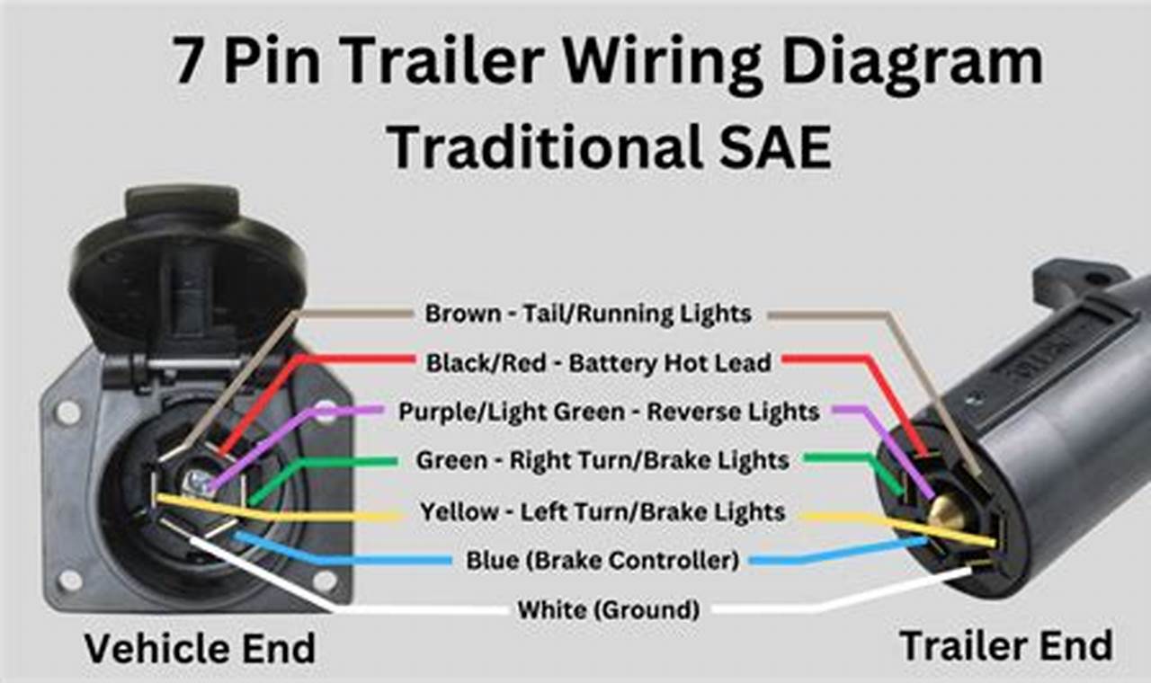
A typical CURT 7-pin trailer wiring diagram illustrates the standardized pin assignments within the connector. While the specific color-coding of wires might vary slightly depending on the manufacturer, the function associated with each pin remains consistent. Here’s a general breakdown: (1) Ground, (2) Tail/Running Lights, (3) Left Turn/Stop Light, (4) Right Turn/Stop Light, (5) Electric Brakes, (6) Auxiliary Power (12V+), and (7) Reverse Lights/Auxiliary. The diagram visually represents how each of these functions connects from the vehicle’s wiring harness to the corresponding circuits on the trailer. Note that some diagrams may reverse the position of Auxiliary Power and Reverse Lights, so always double-check.
Reading a CURT 7 pin trailer wiring diagram involves identifying the pin number and its corresponding function. The diagram will typically show a top-down view of the connector, with each pin clearly labeled. Trace the line from the pin to the circuit it controls. For example, following the line from pin number 3 will lead to the left turn and stop lights circuit. This helps in understanding how the electrical signals are routed. Color-coding, when present, adds another layer of clarity. By correlating the wire color from your vehicle and trailer to the diagram, you can verify proper connections. It is essential to compare the diagram with the actual wiring on both your vehicle and the trailer to identify any discrepancies.
When working with trailer wiring, always disconnect the vehicle’s battery to prevent short circuits. Use a multimeter to test the continuity and voltage of each circuit to confirm proper wiring. Invest in quality wiring tools, such as wire strippers, crimpers, and a circuit tester. Use dielectric grease on the connector pins to prevent corrosion. Check the wiring frequently, especially before long trips. If you are unsure about any aspect of the wiring, consult a qualified automotive electrician. Incorrect wiring can damage your vehicle’s electrical system or create a safety hazard.
In conclusion, understanding the CURT 7 pin trailer wiring diagram is an essential skill for anyone who regularly tows a trailer. By familiarizing yourself with the pin assignments, learning to read the diagram, and following best practices for wiring, you can ensure a safe and reliable electrical connection between your vehicle and trailer. Prioritize safety, use quality tools, and don’t hesitate to seek professional help when needed. A correctly wired trailer is a safer trailer, contributing to a more enjoyable towing experience.
