Introduction
A 4 wires denso alternator configuration represents an advanced vehicle charging setup controlled primarily by the engine control module (ECM) rather than older internal mechanical regulators. Modern automotive electrical systems rely heavily on this multi-wire architecture to optimize fuel economy, manage electrical loads precisely, and reduce mechanical drag on the engine crankshaft. This charging design is commonly found across a wide range of Japanese and domestic passenger vehicles, light trucks, and commercial platforms. Understanding how these four distinct circuits interact improves diagnostic accuracy, prevents catastrophic wiring harness damage, and ensures reliable battery charging under high electrical demands.
💡 Technical Key Takeaways:
- Core Focus: Diagnostic schematic and terminal connection layout for 4 Wires Denso Alternator.
- Target Scope: Field technicians, automotive DIYers, and residential/commercial electricians.
- Safety Rule: Always disconnect the primary power source/battery terminal and verify zero voltage with a multimeter before touching wires.
Core Concepts and Wiring Fundamentals
The 4 wires denso alternator design utilizes a standard multi-pin connector plug alongside the heavy-gauge B+ (Battery Positive) output stud. Unlike vintage single-wire or three-wire self-exciting alternators, this modern unit requires specific inputs and communication lines to operate safely and efficiently. The four individual control wires typically carry designated labels and functions defined by automotive standards set by organizations like the Society of Automotive Engineers (SAE). Each wire plays a non-negotiable role in regulating alternator output, monitoring internal temperatures, and reporting operational status back to the vehicle computer.
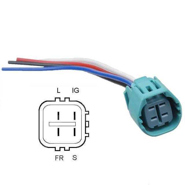
Powering the internal voltage regulation logic requires a dedicated ignition feed, often designated as the IG terminal. Another circuit, known as the S or Sense terminal, monitors system voltage directly at the fuse box or battery to compensate for voltage drop across long wiring runs. A third terminal, labeled L or Lamp, serves as the dashboard charge indicator circuit or digital feedback line to the instrument cluster. The final wire, frequently marked as FR (Field Response) or C (Communication), allows the engine control module to monitor the alternator’s electrical load and command output scaling dynamically.
[Society of Automotive Engineers (SAE)] J1171 — Standard for external ignition protection of marine electrical components, establishing strict guidelines for alternator spark suppression and multi-wire terminal durability.
Diagram Explanation and Key Components
Reading a schematic for a 4 wires denso alternator requires identifying both power distribution symbols and low-current logic lines. The heavy primary output wire connects directly through a fusible link to the positive battery terminal or starter motor main post, carrying the full generation current. The multi-pin control connector uses distinct pin layouts that vary slightly between manufacturer applications, making reference to proper Vehicle Wiring Diagrams essential during diagnostic procedures. Symbols on these schematics typically differentiate between power feeds protected by fuses, switched ignition circuits, and pulse-width modulated control lines routed directly to the powertrain control module.
Wire color codes on these harnesses differ depending on regional manufacturing standards and vehicle brands. Technicians working in North America adhere to SAE color conventions, whereas vehicles assembled in the UK or Europe may follow alternative standards. Tracing each line requires verifying pin cavities within the plastic connector housing rather than relying solely on exterior insulation color. The internal rectifier bridge, rotor windings, and solid-state regulator form a compact assembly hidden beneath the rear housing, communicating instantly with the vehicle computer network through the designated control harness.
Common Problems and Troubleshooting Methods
Diagnosing a failing charging circuit begins with a systematic evaluation of voltage drops, continuity tests, and visual inspections of the multi-pin connector. A common point of failure involves oil contamination entering the connector cavity from leaking valve cover gaskets, leading to high-resistance corrosion on the delicate control terminals. Technicians frequently encounter broken sense wires, blown instrument cluster fuses, or internal regulator faults that prevent the alternator from exciting properly. To explore standard diagnostic methods for complex electrical paths, consult professional guides on Wiring Troubleshooting.
Testing a 4 wires denso alternator involves back-probing the connector while the engine runs to verify reference voltages and signal integrity. The ignition feed should display battery voltage with the key in the run position, while the sense wire must match actual system voltage measured directly at the battery posts. A missing or erratic field response signal often points toward a damaged harness or a failing ECM driver circuit rather than a defective alternator unit. Always isolate the battery before disconnecting major power cables to prevent accidental short circuits against surrounding chassis components.
Practical Tips and Safety Considerations
Working on high-current automotive charging circuits demands strict adherence to safety protocols to prevent severe electrical burns or component destruction. Always disconnect the negative battery terminal before servicing alternator connections, as the main B+ stud maintains an unswitched, unfused connection directly to the battery storage system. Ensure replacement wiring harnesses match the original gauge size and temperature rating, especially within cramped engine bays exposed to intense exhaust manifold heat. For foundational knowledge regarding schematic interpretation, review the principles outlined in Wiring Diagram Basics.
Avoid “full-fielding” modern computer-controlled alternators with jumper wires, as this bypasses critical thermal and voltage safeguards built into the regulator logic. Doing so can easily generate voltage spikes exceeding standard limits, destroying sensitive vehicle modules, airbags, and entertainment systems. Inspect locking tabs on the four-pin connector during reassembly to ensure environmental weather seals seat properly against moisture intrusion. Proper mechanical torque on the main output stud prevents high-resistance connections that generate excessive heat and potential fire hazards.
Conclusion
Mastering the intricacies of a 4 wires denso alternator transforms a frustrating electrical diagnostic challenge into a straightforward, logical procedure. By recognizing the specific functions of the ignition, sense, lamp, and field response circuits, technicians can quickly isolate whether a fault originates within the alternator itself, the control module, or the wiring harness. Maintaining clean connections, verifying correct wire sizing, and utilizing proper schematics guarantee long-term system reliability. Diligent testing practices protect expensive electronic components and ensure dependable vehicle operation across all driving conditions.
Quick Wiring Specifications & Terminal Guide
| Component / Circuit | Standard Wire Gauge | Recommended Protection |
|---|---|---|
| Control & Trigger Signals | 18 – 20 AWG | 5A – 7.5A Inline Fuse |
| Standard Auxiliary Load | 14 – 16 AWG | 15A – 20A Circuit Breaker |
| Main Power Feed / Supply | 10 – 12 AWG | 30A – 40A Heavy-Duty Relay |
Images References